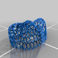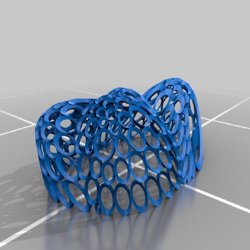

This a printable STL file of the Archimedean Pavilion.
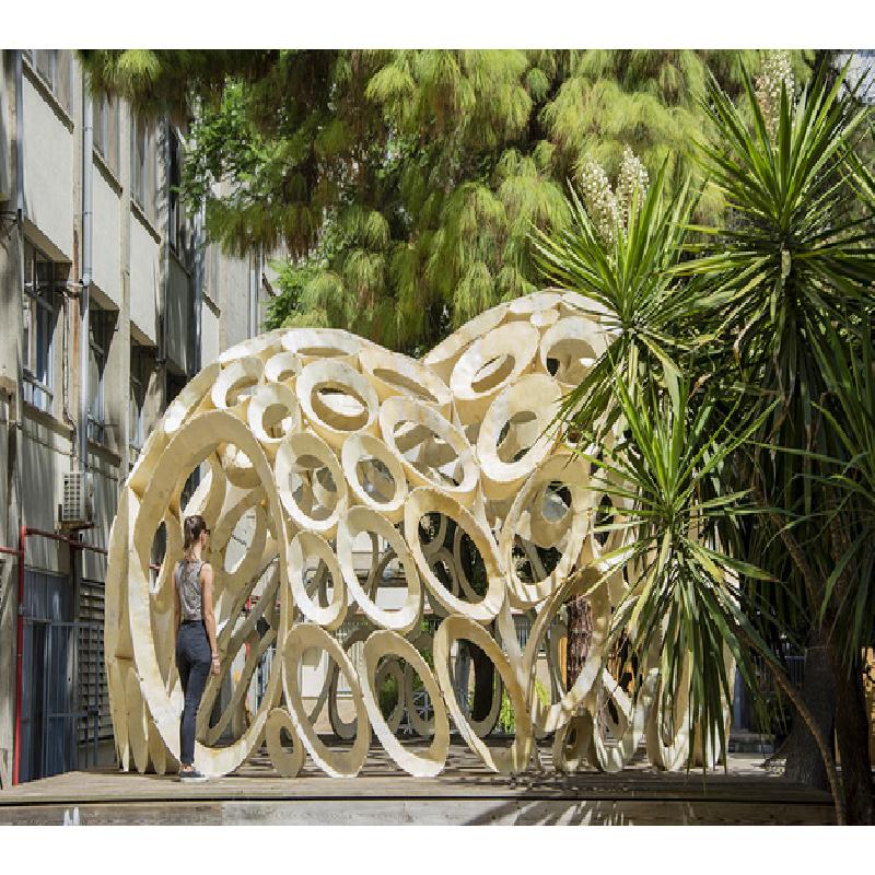
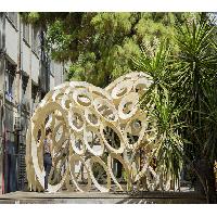
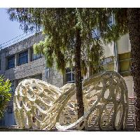
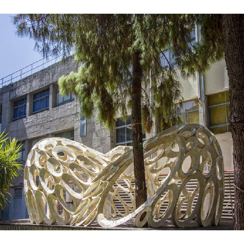
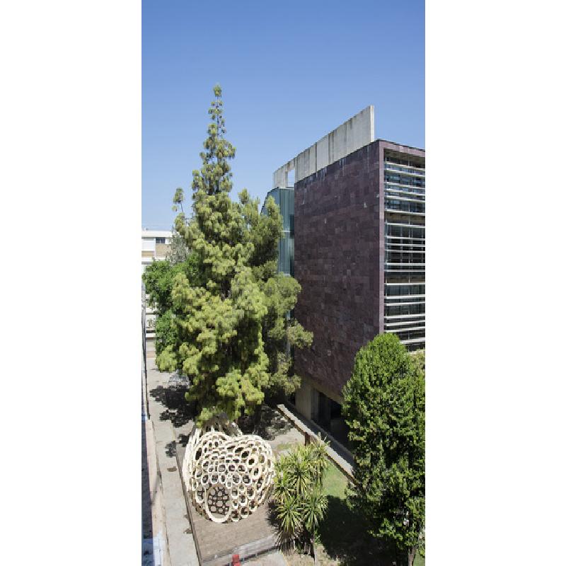
The Archimedean is a ten-point-five-meter-long, six-meter-wide and three-point-five-meter high pavilion, which was installed on the wooden platform between the schools of Architecture and Building Engineering in the University of Seville (Spain). As in the Caterpillar project, the origin of this work lies on the combination of geometric research and teaching innovation, with the intention to carry out a generative model to be used as an Architectural Geometry exercise for both schools' students.
The starting point for this project is the projective interpretation, already made by professor Gentil-Baldrich (Gentil Baldrich, 1997), about the proposition 12 stated by Archimedes of Syracuse (287-212 B.C.) in his work “On Conoids and Spheroids” (Archimedes, 1897). That came to say that the planar section of a paraboloid of revolution, produced by a plane neither parallel nor perpendicular to the axis, is an ellipse. And that the minor axis of the ellipse is equal to the perpendicular distance between the two lines, parallel to the axis of the paraboloid, which pass through the extremes of the major axis. This is just a particular case of a generalised theorem affecting all quadrics of revolutions generated around the axis containing the foci (Martin-Pastor, Narvaez-Rodriguez, & Hernandez-Macias, 2016).
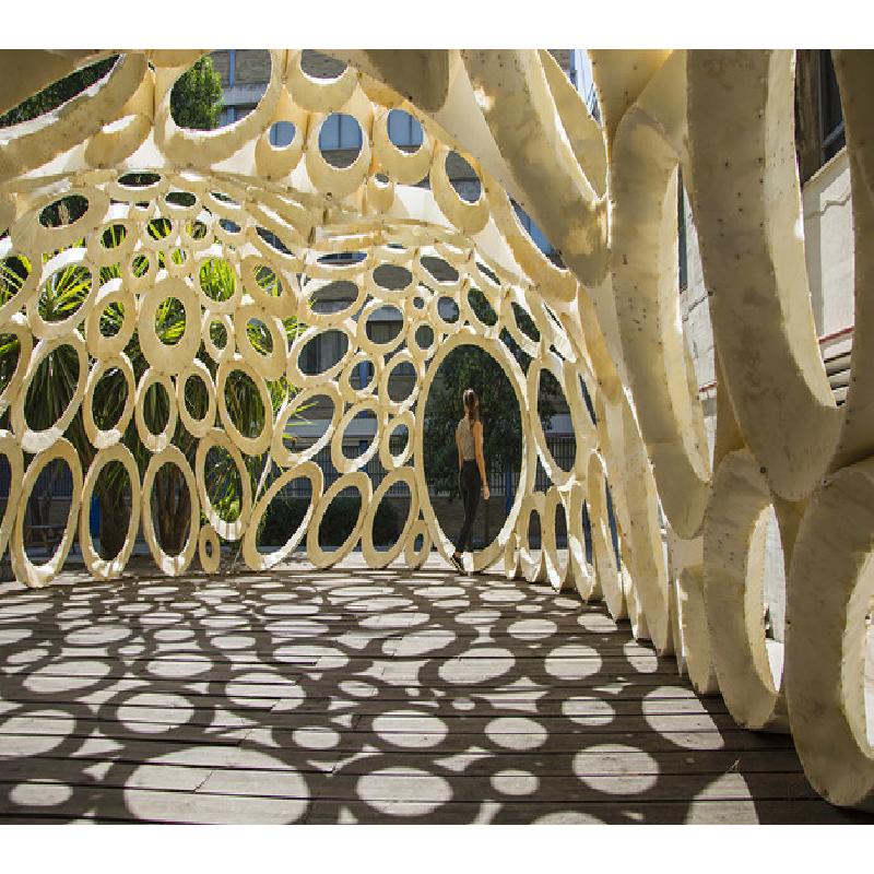
From a projective point of view, the Archimedean statement could be formulated; by using the parallel projection defined by the direction of the axis of the paraboloid, any circle on a plane perpendicular to the axis of the paraboloid is projected onto the paraboloid’s surface as an ellipse, which is a planar curve. This property means, among other interpretations, that any circle-packing arrangement can be projected onto the paraboloid to obtain a discretisation of the surface based on planar elliptical faces or rings tangent to each other at various points of the boundary.
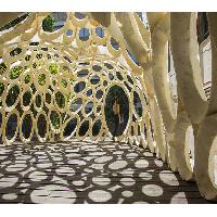
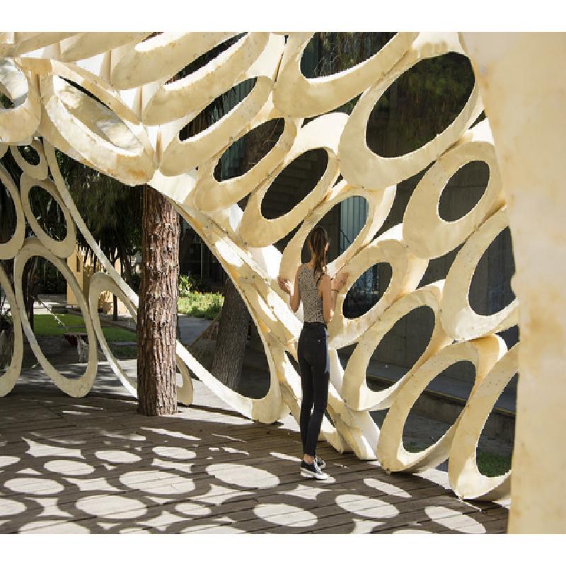
Working on that concept to discretise rotational parabolic surfaces, the Archimedean Pavilion was originally conceived as an exploration of the different spaces generated by four rotational paraboloids under certain conditions with variable position, orientation and parameter. Therefore the result is a single space enclosed by 4 fractions of rotational paraboloids, which can be discretised by using the aforementioned projective interpretation.
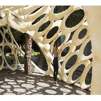
The main problem laid on how to materialise the elliptical rings with enough stiffness to generate a kind of porous rigid shell for every paraboloid. The solution chosen, among the infinite possibilities, was based on lightweight conical components (Narvaez-Rodriguez & Barrera-Vera, 2016), which resulted in an very efficient method compare to alternative solutions based on rigidifying the rings by thickening the boundary, since the amount of needed material is about twenty times lower to provide the same rigidity.
Every component is made up of three fractions of conical surface, therefore developable, generating a triangular cross section. It is a system that can be fabricated with the use of laminar materials, thus it is simple to execute and normally fabricated from standard sheets or panels cut with a laser cutter or CNC milling machines. The success of the constructive system, to achieve consistency between the model for the structural analysis and the real execution of the components, relies on the appropriate execution of the three types of joints produced in the structure: (1) the surface seam of the surfaces, which must not coincide with the generators of the cones. (2) The joints between the three conical fractions of every component, which must be executed to ensure continuity. (3) The connection between different components, which should coincide with the tangency line, although the tests carried out revealed the successful use of two points of the line solved with bolts.
Although the system is thought to be carried out with metal sheets or thin wooden panels, the budget limitations took the prototype to be fabricated with one-millimetre-thick sheets of polyethylene (HDPE), whose laminar behaviour is similar in terms of fabrication and assembly, but easier and safer to be manipulated by students. Nevertheless, this material holds some properties which render it as non-appropriate for installations intended to last; non-linear deformation, variable behaviour according the temperature and, mainly, creep or cold flow, which makes it keep deforming when exposed to high levels of stress for long-term periods. In this case the sponsorship of Dow Chemical to fill the components with polyurethane foam allowed the prototype to be exposed for a longer period.