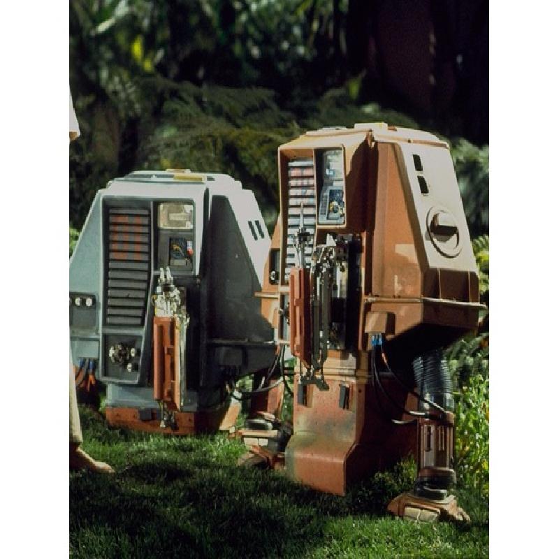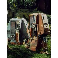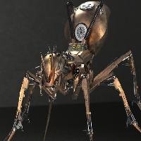

This is my rendition of a robot drone from the 1971 science fiction film Silent Running.
https://www.youtube.com/watch?v=R-OBV49gvmk
(Scrub the video to about 1:25)
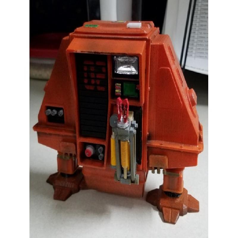
My aim was not for it to be shiny and new... It is a dirty maintenance drone. Cruddy corners, leaking fluid. A bit beat up.
There are a lot of parts to be glued together. I suggest using JB Weld 24hr epoxy (not the 5 minute stuff). It's a fun project to craft.
If you print the THING files you will have a complete set of parts. Alternatively you can download the .stl files and load them yourself. Assembly will go easier if you follow the suggested process, outlined in the illustrated pics.
This was printed on the Makerbot Mini.
Printer Brand:
MakerBot
Printer:
MakerBot Replicator Mini
Rafts:
Yes
Supports:
No
Resolution:
Default
Infill:
5%
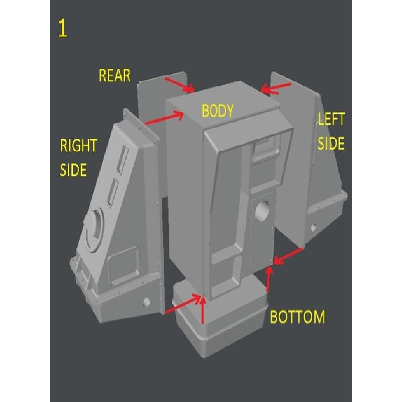
Assembly suggestions as shown in the diagram pics.
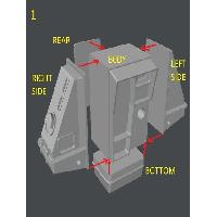
(1) Glue the Left,Right and Bottom to the Main body. I suggest you fill any gaps between the parts with filler. I just used wood glue.
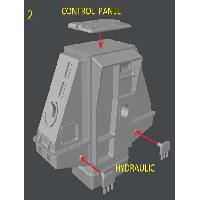
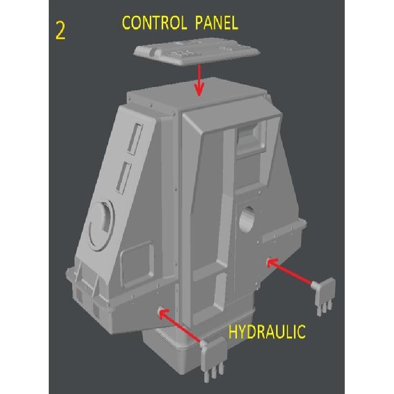
(2) Glue the control panel on the top,and the hydraulic connector pieces in the front holes.
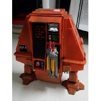
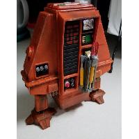
At this point I suggest you finish the post-print processing of all parts. A good sanding,paint and sealer. For the body I used an airbrush to apply the acrylic base orange color,browns and blacks for shadows/dirty areas and speckled-splattered with black.Then followed with a few layers of Miniwax Polycrylic to make the paint more durable.
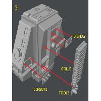
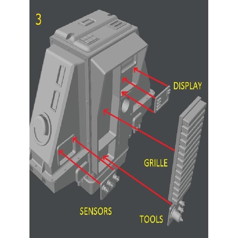
(3) Glue the rest of the front pieces: The grille,display,tool and sensor panels.
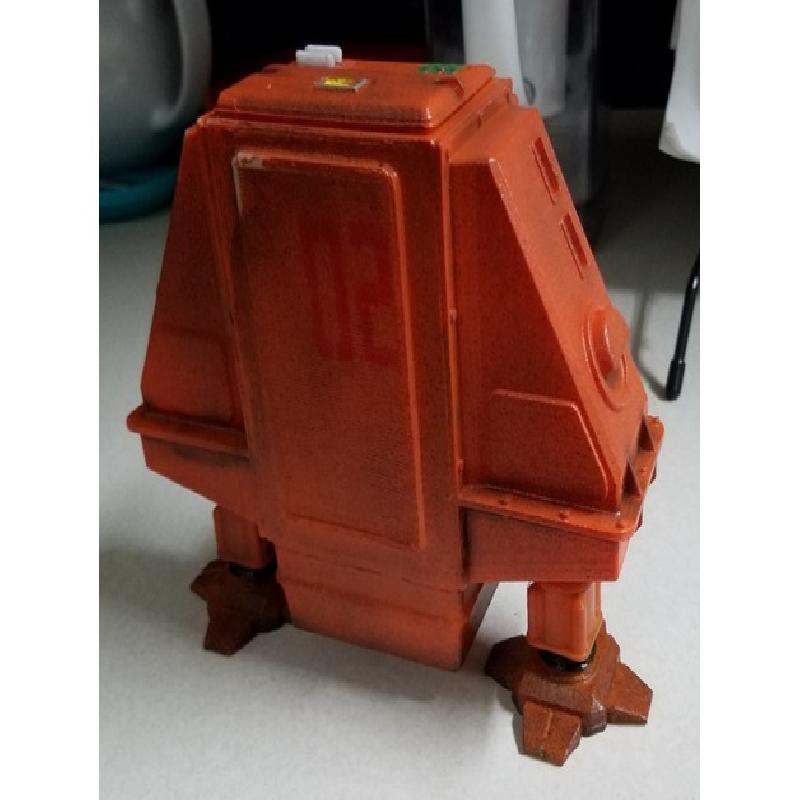
I included a pair of "02" stencils.Use the small one to stencil the front grille, and the larger stencil for the rear cover.
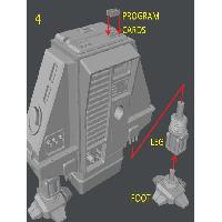
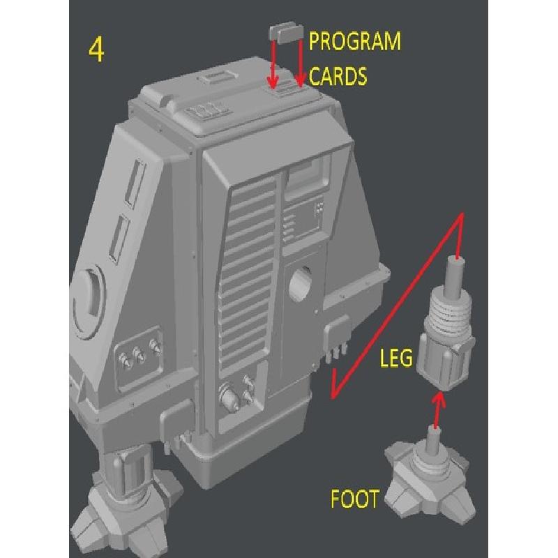
(4) Glue the feet to the legs. Note one side of the leg has a flat spot which should face the front. You can glue "hydraulic" lines to the flat areas in the future for a more authentic look if you wish. Also glue the program cards into the slots in the top control panel.
The glue for the feet and legs should cure so the body leans slightly back (not slumping forward).
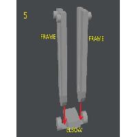
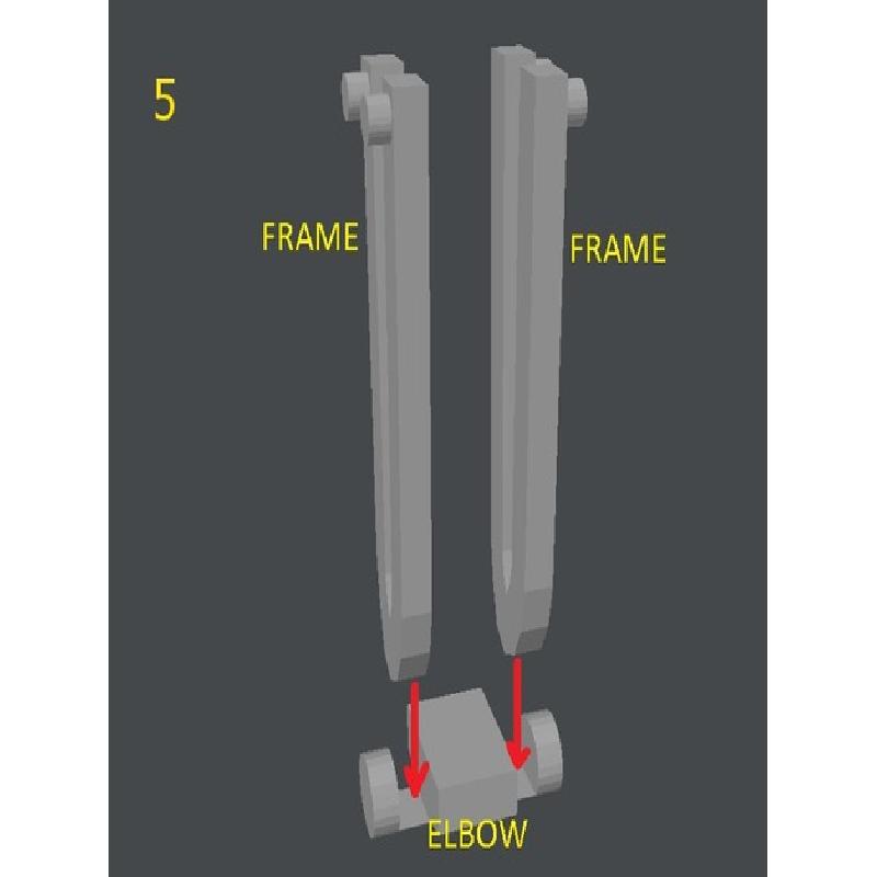
(5) Begin assembling the mechanical arm with gluing the ends of them into the elbow slots. I suggest completing the entire arm assembly while the JB Weld epoxy is still soft and adjustable.
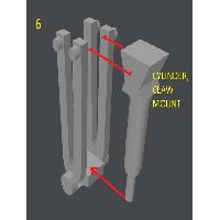
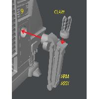
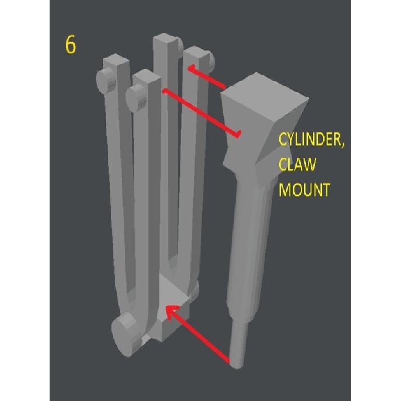
(6) Glue the top of the Cylinder claw mount to one end of each frame as shown, and the end of its cylinder to the elbow.
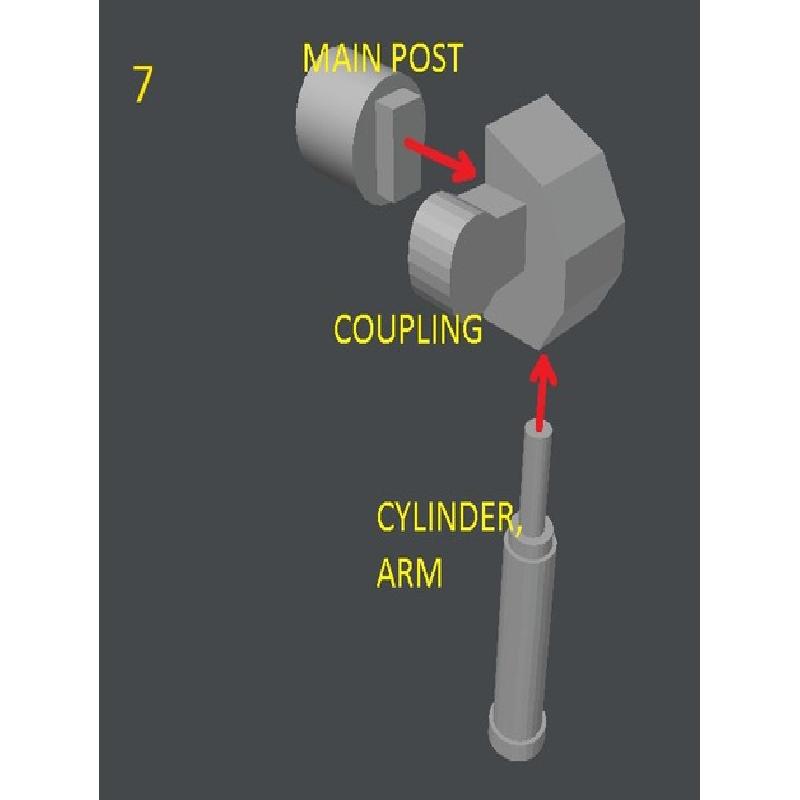
(7) Glue the main post into the slot in the coupling. Glue the end of the cylinder arm into the hole in the coupling. Note the bottom of the cylinder arm is ROUND.
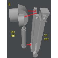
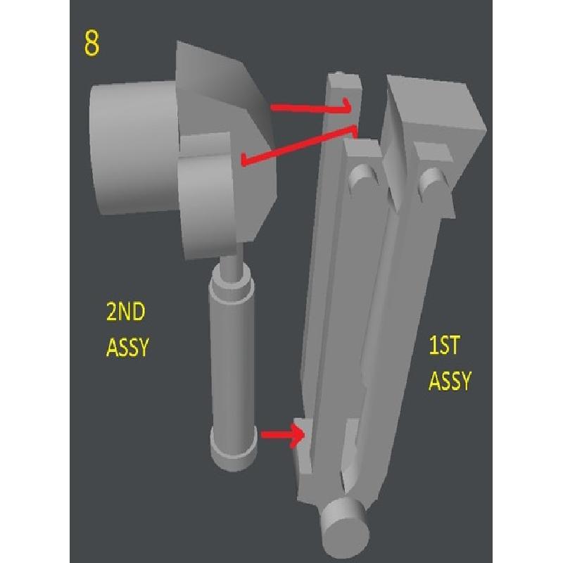
(8) Glue the coupling onto the other ends of the frames, and glue the bottom of the arm cylinder onto the elbow.
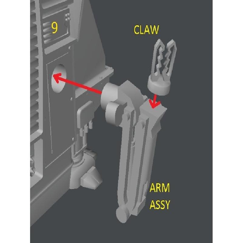
(9) Glue the main post into the body, and the claw onto the arm assembly.
The frames near the elbow should press against the main body. Apply a bit of glue there too.
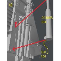
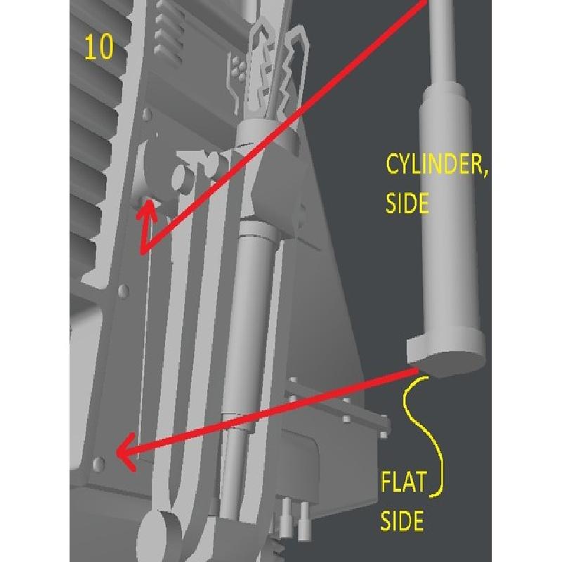
(10) Glue the end of the Cylinder,Side into the hole in the coupling. The Cylinder,Side has a flat spot on its wider end. Glue the flat spot onto the main body. Ensure the arm is square to the body before the glue sets.
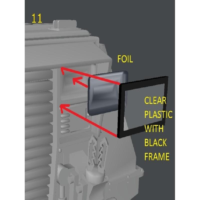
(11) Cut a small square of tin foil to fit inside the light socket area and press it to form-fit it into the light socket with the tip of your finger. Remove the foil and trim the excess, then glue it into the light socket.
Cut a small square of clear plastic to fit as a head light lens. I used some clear plastic from vacuum formed packaging. Draw a black frame around the edges of the plastic and glue it over the tin foil.
Enjoy.
I used Newtek's Lightwave 3D to design this and Gimp to create the illustrations.