
Hi guys
First of all I want to apologize for my English, so if I made some terrible mistakes or something does`t make sense please let me know:)
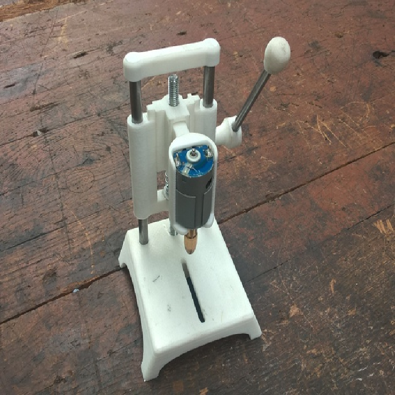
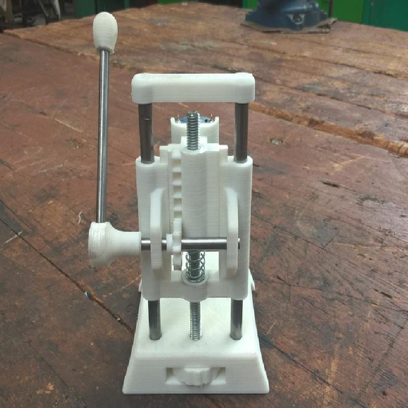
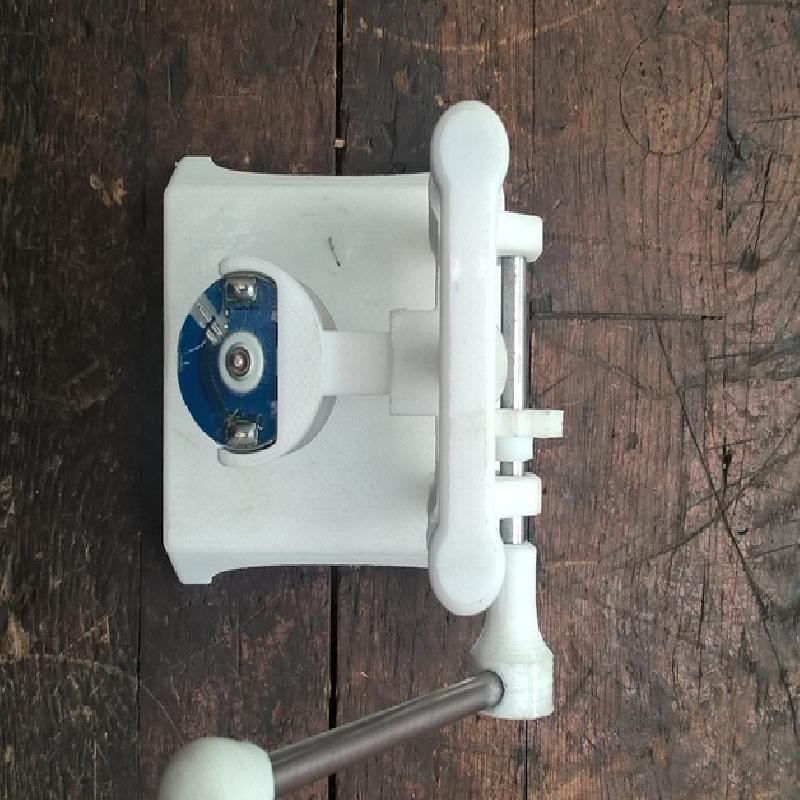
This is the PCB mini drill. It`s my first design so if you come across some problems feel free to contact me or leave a comment. Also I am sharing my SolidWorks 2014 files so if you want you can make changes to model of your own. The motor holder part is designed to be removable, so it can be redesigned to hold another type of the motor.
The following hardware will be needed to assemble the drill:
M8 (13mm) nut
M8 x 130mm threaded rod (1x)
M8 x 150mm rod (2x)
M6 x 70mm rod (1x)
M6 x 100mm rod (1x)
Spring (1x)
Motor (39mm in height, 29mm in diameter) , or some other but the motor holder part must be changed to fit different motor ( You can find these motors in some old printers )
and search for this on ebay :
8Pcs 0.5-3mm Small Electric Drill Bit Collet Micro Twist Chuck Tool Kit CC
Assembly instructions :
Print all necessary parts ( I suggest using 30% honeycomb infill , supports only if the are needed and 10mm brim at least for the body part)
Get ready the metal parts and the motor
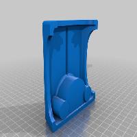
You fill need to finish the body part with 8mm (8.1 or 8.2) drill, to fit the 8 mm rods tight but free to move.
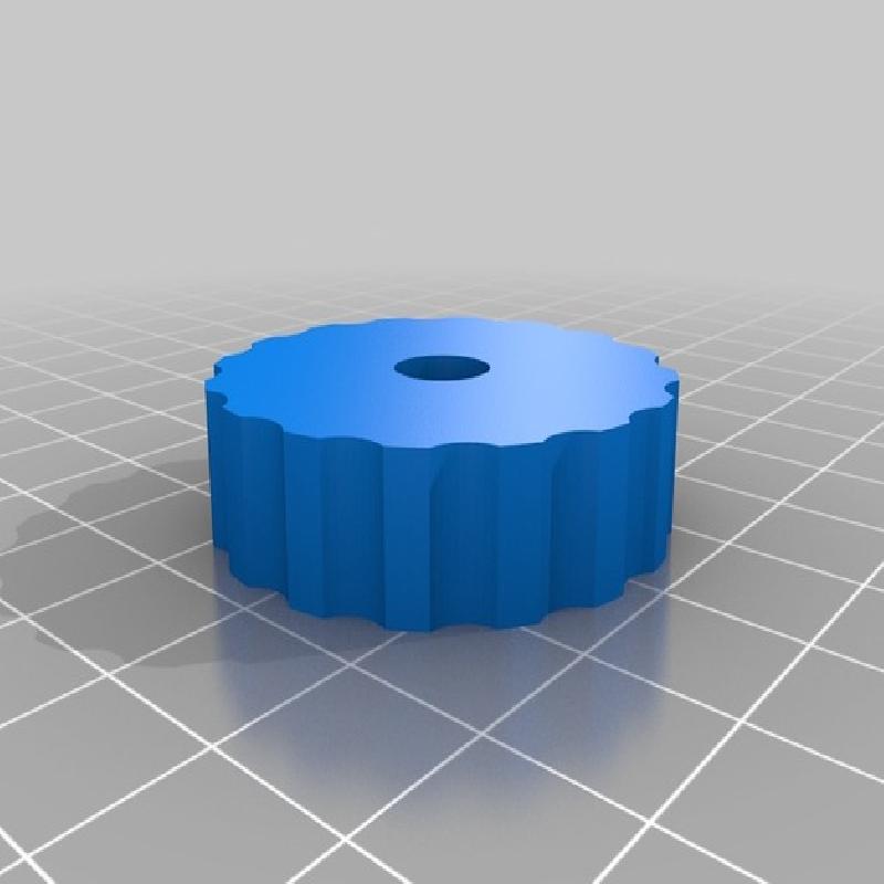
Stick the 8 mm rods to the stand, insert height_wheel into back of the stand and insert the treated rod trough middle hole on the stand a try to screw it into the height_wheel ( no need to glue it )
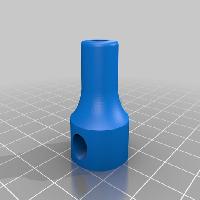
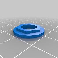
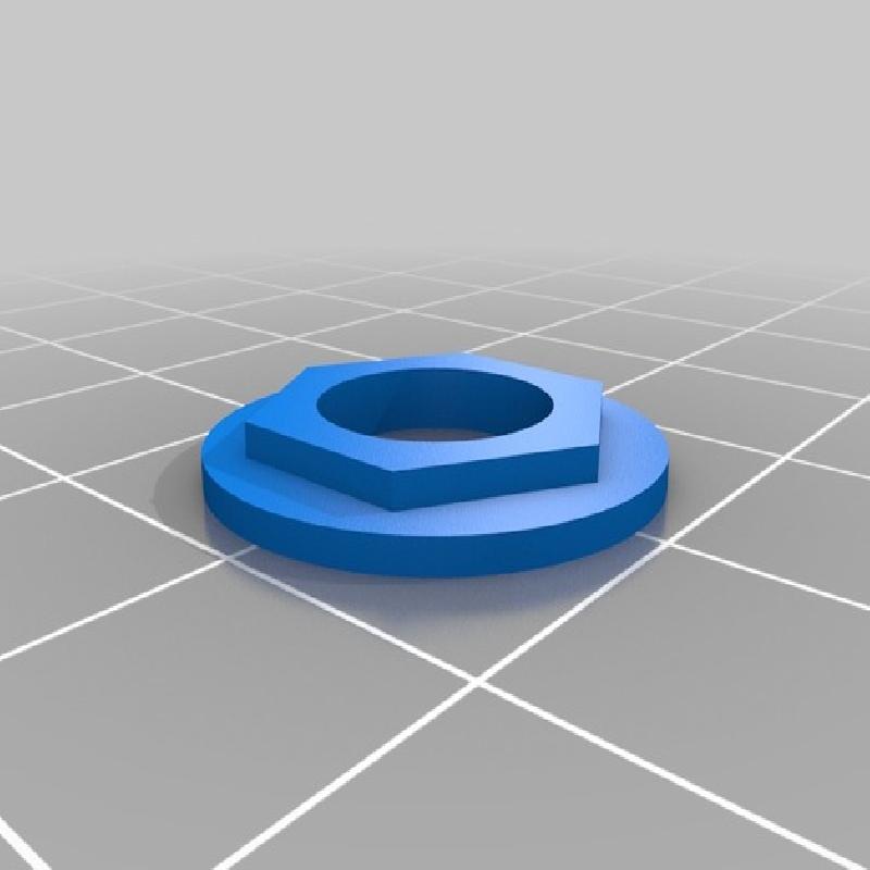
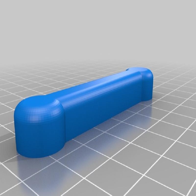
Fit the 8mm nut to the body part, close and glue it with nut_cup (with acetone).
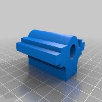
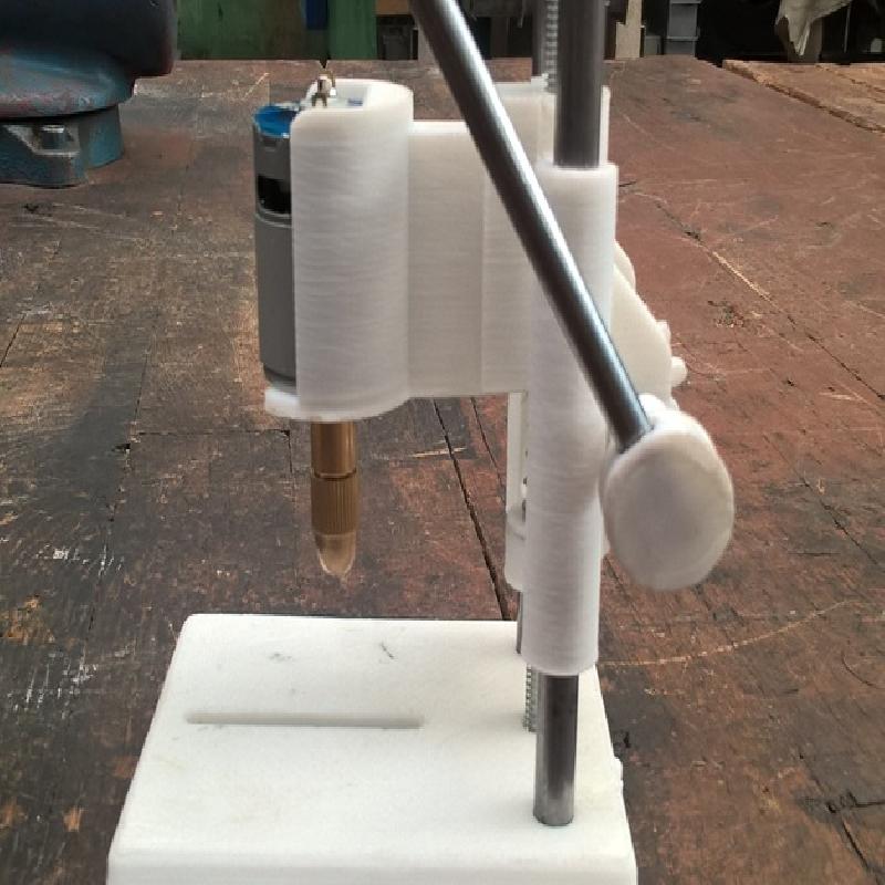
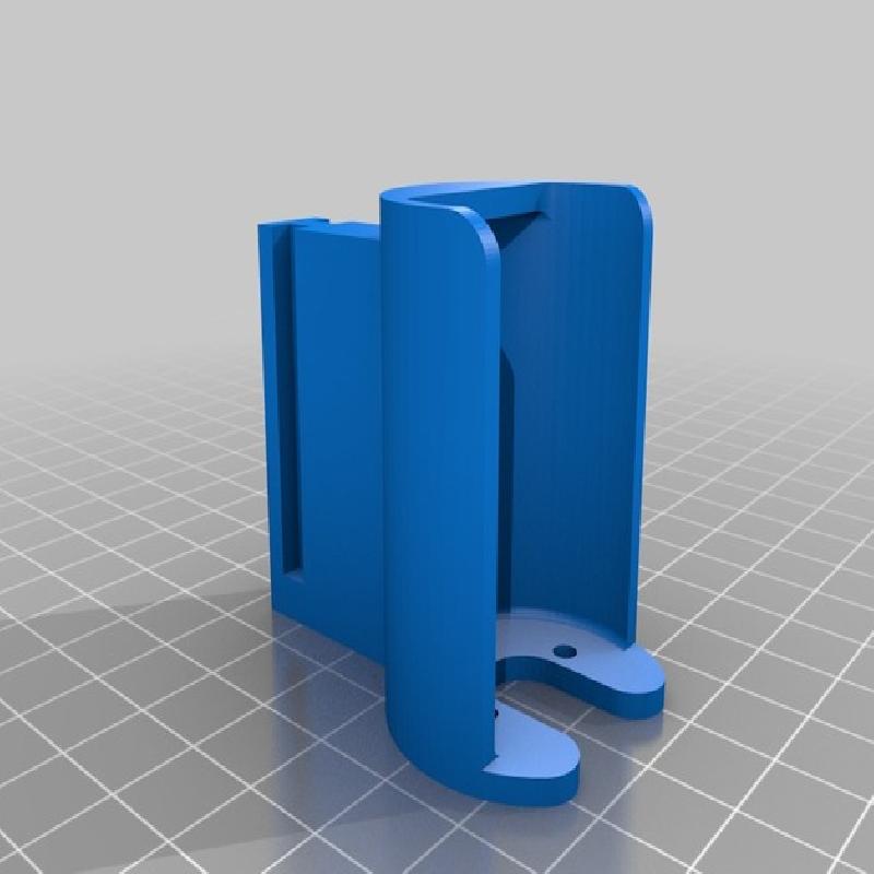
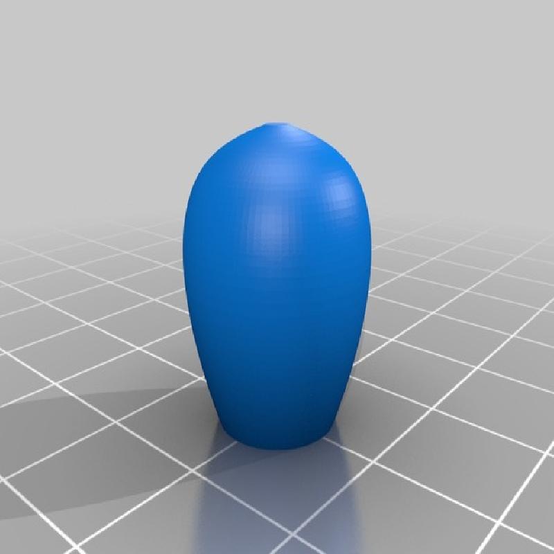
Insert motor to the motor holder and then try to put on the drill head,
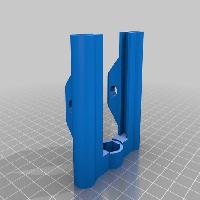
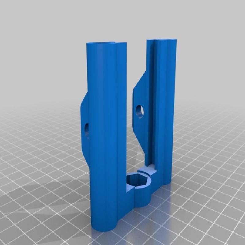
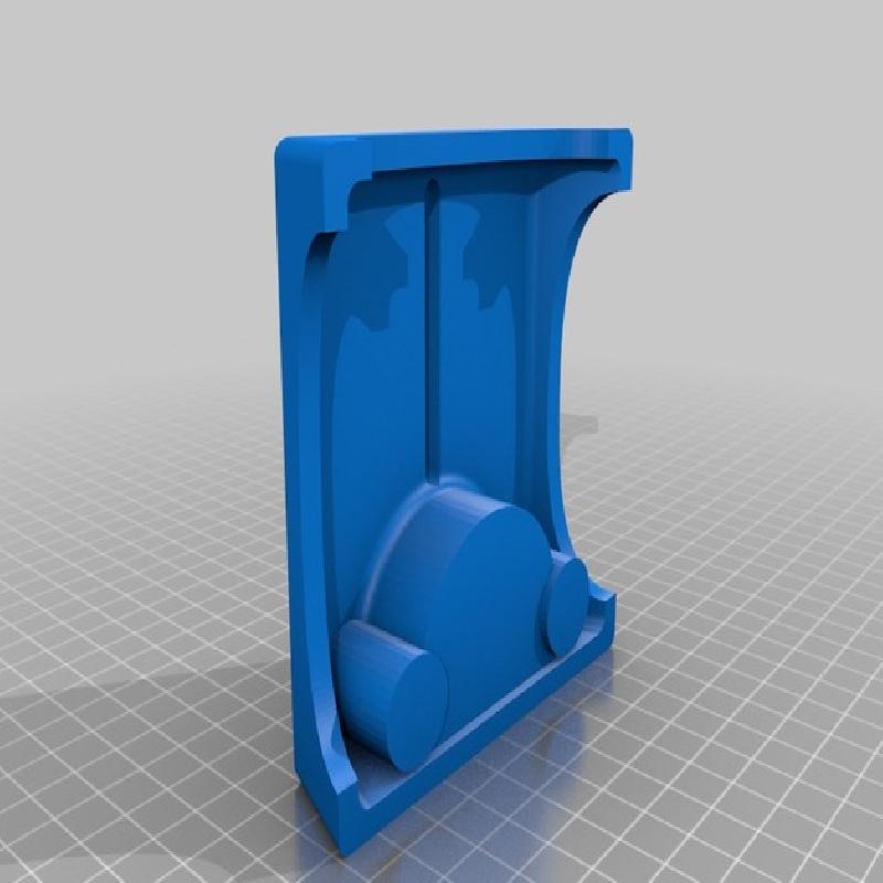
Connect motor holder to the slider part. This is designed to be tight fit so before you try you should use sandpaper on both parts and finish the surface a little.
Put the body on the stand , put on string and insert slider with motor.
Put the top_end part on.
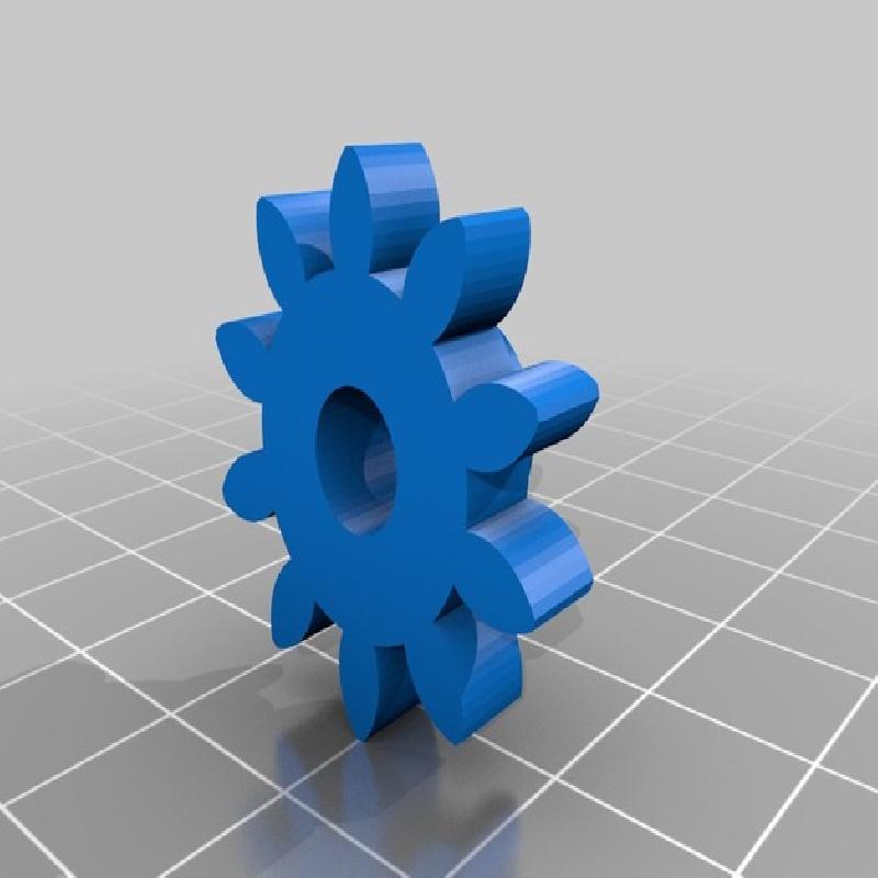
Now you must insert gear to the 6x70 metal rod. This is kind of tricky. Drill the hole on the gear with 6mm (6.1 or 6.2) drill to make tight fit with the rod. First insert the rod trough one hole on the back of the body part, then slide on the gear and then try to push the rod into the opposite hole on the body. ( You can chose on witch side you want to have handle. Left or right.)
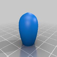
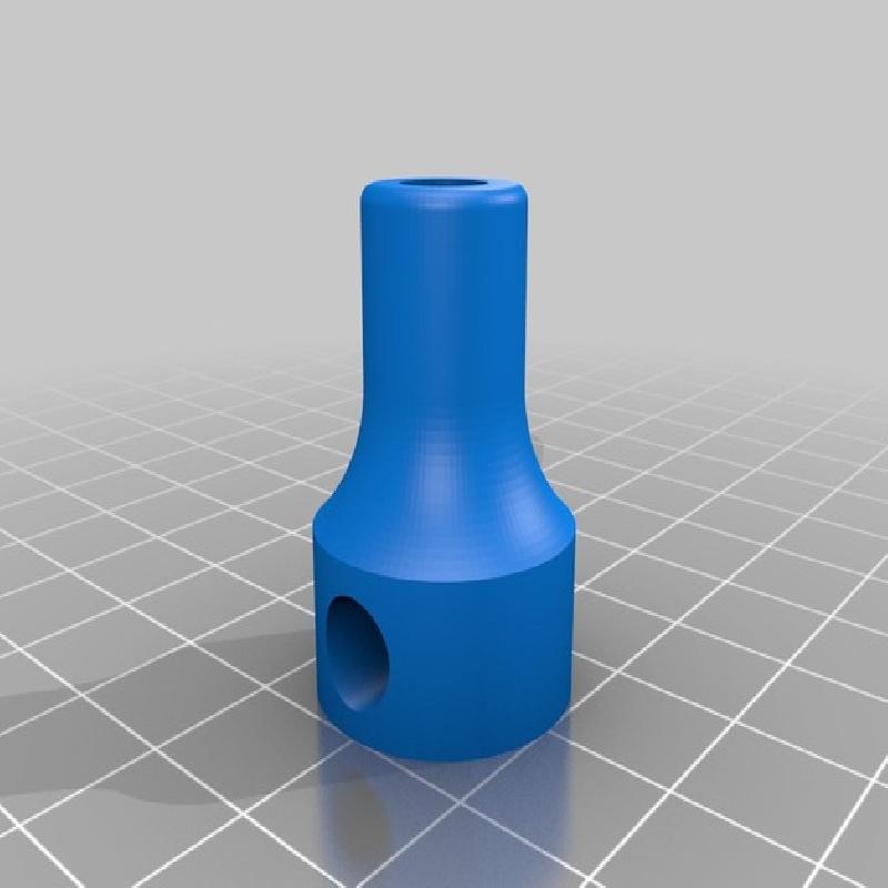
Complete the handle by inserting handle_clutch on the longer end of 70mm rod, insert the 100mm rod into the clutch and put on the handle_end part.
12 Now you have to fix somehow the gear to the 70 mm rod. This is up to you ( until I remake this part to be more easy to assemble) . I drilled 2.5 mm hole trough the gear and the rod and glued in a piece of 2.5 mm welding wire. Otherwise the gear may be sliding when the force is applied to the handle.
The drill should be complete now, Last thing you must do is solder some wires to the motor,connect to 12V (1,5A) power source, and try to drill some holes :)