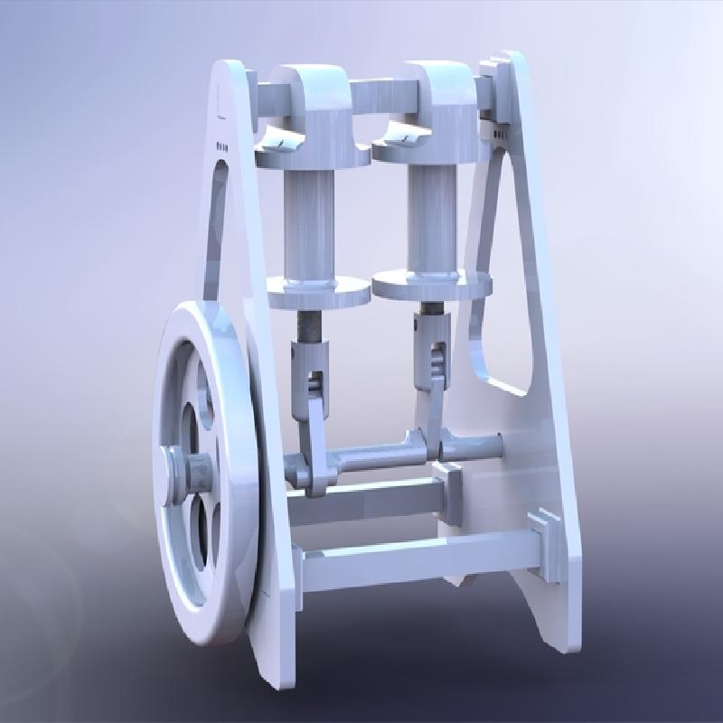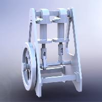

This is a functional model of solenoid engine. I already made one and for now it is working fine. I am sharing my SolidWorks 2014 files so if you want you can adjust the model as you see fit.
The following hardware will be needed to assemble the motor:
6mm balls for the flywheel ( not necessary, motor should work without them )
Coil wire ( I used 1mm wire )
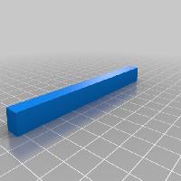
2x 8x40 metal rod
2x Rectifier diode
1x Capacitor 1000u/25V
2x Micro roller switch - you can find it on ebay :
10Pcs KW12-3 Micro Roller Lever Arm Normally Open Close Limit Switch
Assembly instructions :
Print all necessary parts.
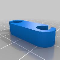
2x Conecting_rod
2x Piston_onnecting_rod
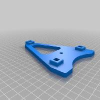
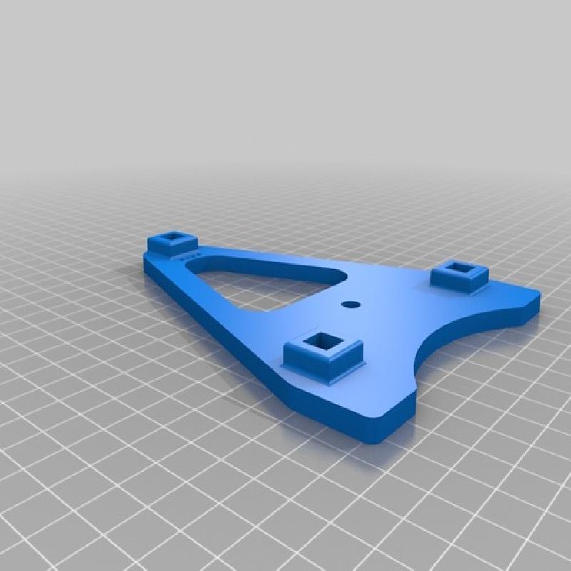
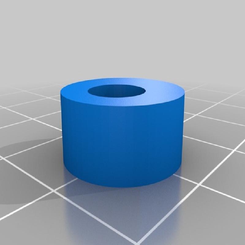
2x Coil_holder1
2x Coil_holder2
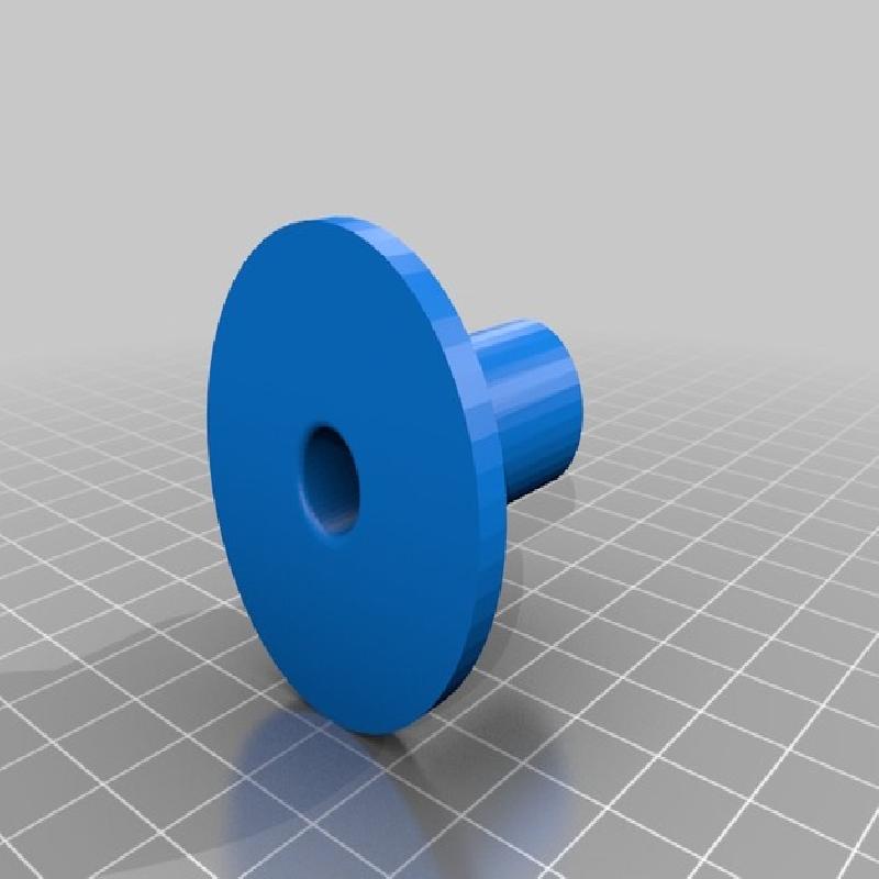
1x Commutator
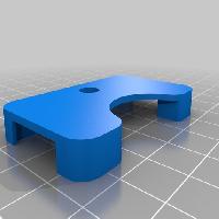
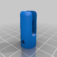
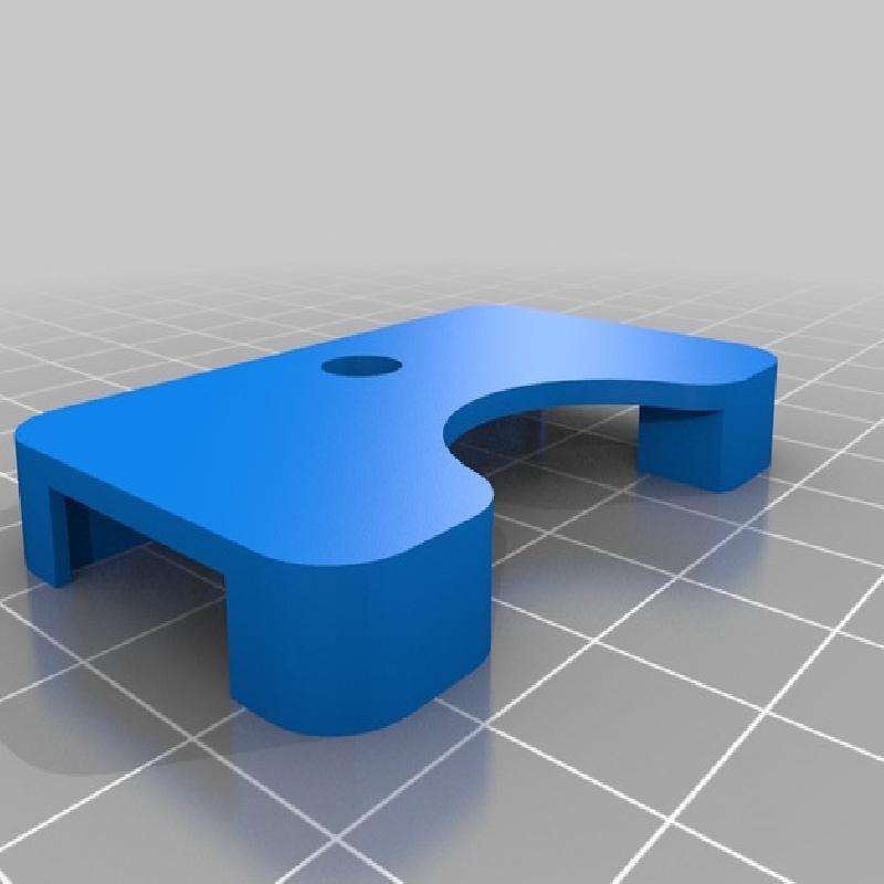
2x Piston_holder
1x Conecting_rod_top
2x Wall
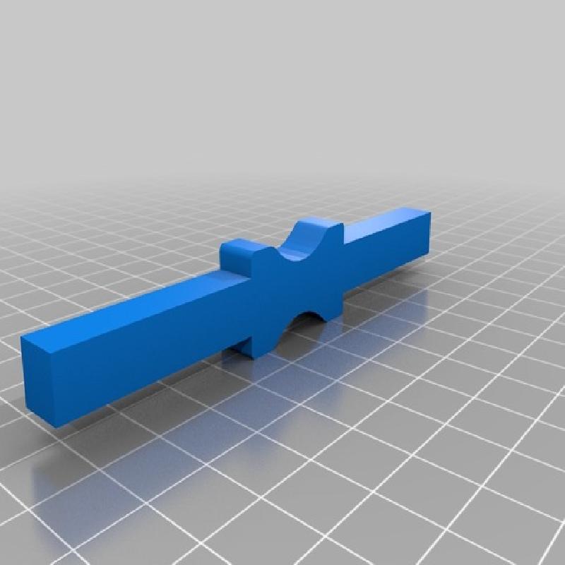
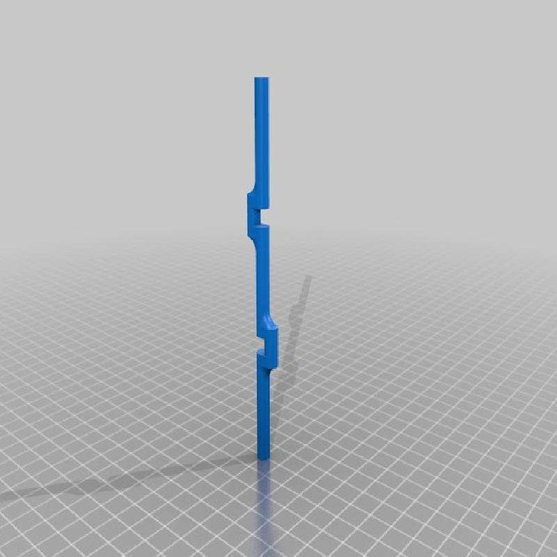
1x Crankshaft
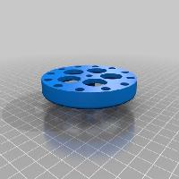
1x Ignition_wheel
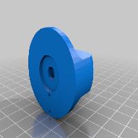
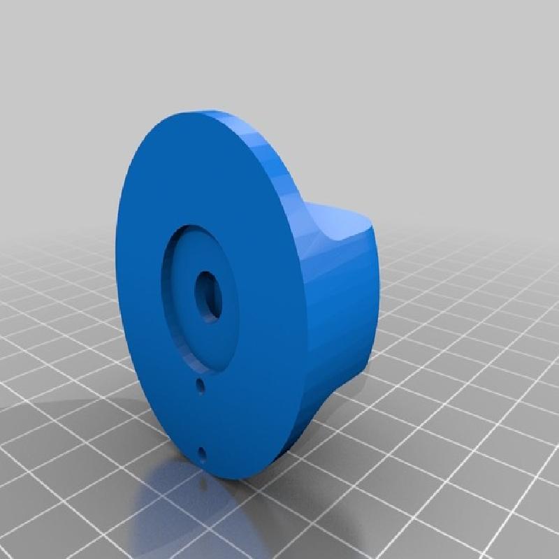
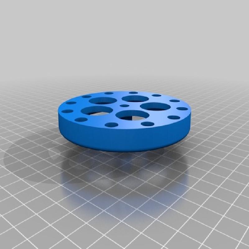
1x Flywheel
( I suggest using 30% honeycomb infill , supports only if the are needed )
Glue together Coil holder1 and Coil holder2 parts with acetone. Then you will need to wound coils on them.
Connect the metal rod with piston_holders ( I drilled 2.5 mm hole to the pistons and used piece of 2.5mm welding wire as a cotter pins, but making a thread on the end of the rods will works as well I think. If someone find better way how to attach piston to the piston holder feel free to let me know )
Connect piston_rods with piston holders and the crankshaft. Everything should move freely so before you do that use some sandpaper and finish the parts.
Attach both coil on the top_conecting_rod, insert the pistons to the holes in coil holders (assembled with crankshaft and piston rods ).
Then you can put everything together ( Walls to each side, crankshaft should fit trough the holes )
Glue on the flywheel to crankshaft and commutator to the opposite wall ( Insert the metal balls to flywheel before attaching it if you have them )
Insert switches to the commutator and attach ignition_wheel. The you need to solder everything down. Don`t forget to connect diodes to the coils. (I will add the electric scheme later )
Then you must find the right spot for ignitions by turning the ignition_wheel. ( This is the hardest part. I had to print many of these ignition_wheels to get it working right ).
All done. If all is properly connected motor should run. I needed at least 15V (3A) to get it running. Good luck ! :)
I welcome any suggestions how to make this model better so feel free to email me ,send PM or leave a comment. Thanks!
Printer:
DaVinci AiO
Rafts:
No
Supports:
Doesn't Matter
Resolution:
0.2
Infill:
30%