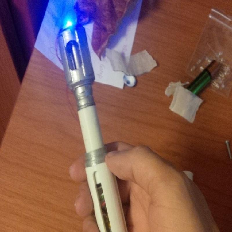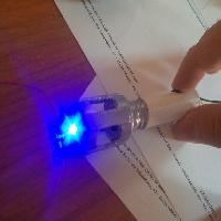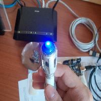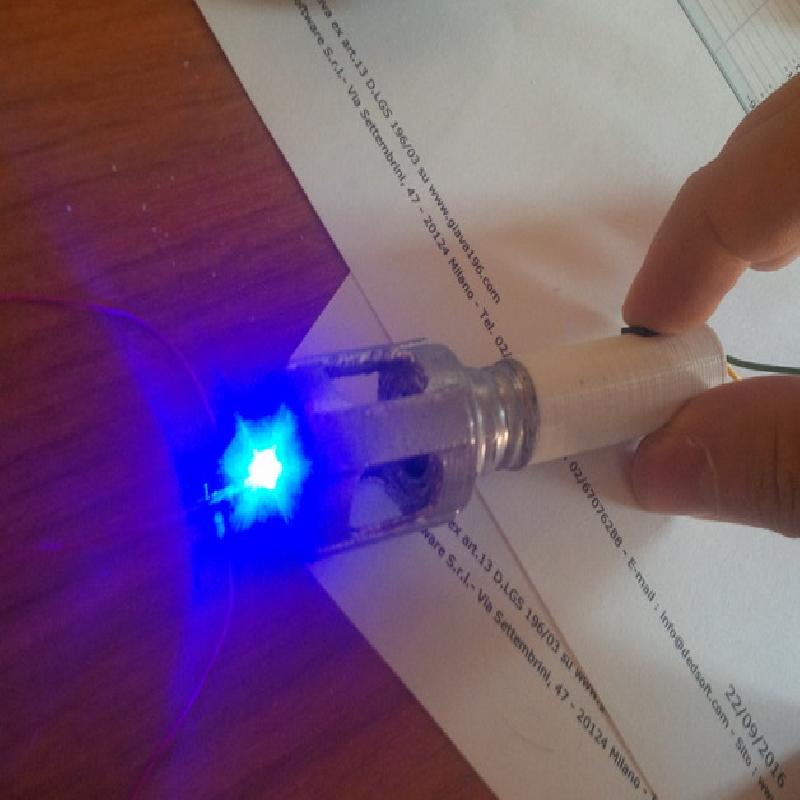

I dediced to gift the 10th sonic screwdriver to a friend of mine who likes the series a lot, and i wanted to make it a little special, so i edited WPilgrim's (credits to him for the original design) version. If you buy a bright led you can use this as a torch too!
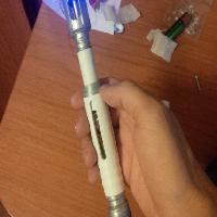
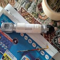
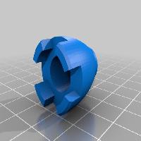
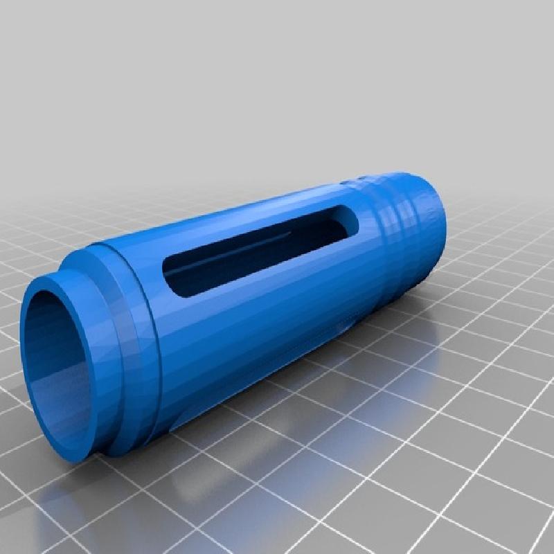
I also edited the slider to better match the original tv show's screwdriver.
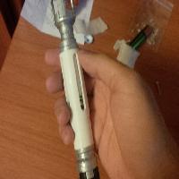
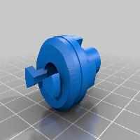
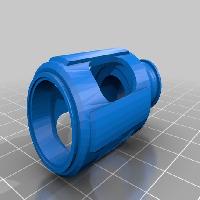
Unluckily I don't have transparent filament, so the I made the "inner outer" central part thicker than the original, otherwise it would have been printed with walls 1 perimeter line thick, not the best with standard filament
I'll make an instructables guide soon for the assembling process. Please see the "How i designed this" section for more context.
All files have been automatically repaired with Netafbb, should there be any problem please do let me know.
If you print one, be sure to hit the "I made one" button!
Printer Brand:
RepRap
Printer:
Prusa i3 R2
Rafts:
No
Supports:
Yes
Resolution:
0.1 - 0.14 - 0.2, depends on the piece
Infill:
35%
Painting
I've used Humbrol enamel paint (I don't suggest using acrylic), silver (# 11) and midnight blue (# 14)
Reapply once or twice to make banding less visible.
Assembling
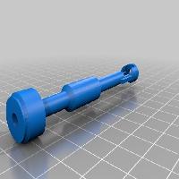
Solder a long piece of wire to the led anode and a 30 ohm resistor (actually I've used 2x15ohm) to the other leg. solder some wire to the other side of the resistor. Push the wire through the "inner inner" hole until the led head is inside.
Insert the "inner inner" in the "top", and then in the "inner outer".
Pass the wire soldered to the resistor through the switch housing hole, cut it so that only about 1.5 cm stick out of the hole, and solder it to the switch common pin. Solder a piece of wire to the Normally open pin, then run the cable inside the housing and through the bottom hole. Now you should have 2 cables going outside the slider.
Remove the metallic lever of the switch, there's no space inside for it. Push the switch inside his housing, making sure the button faces towards the top (where the led is housed). When you push it in the extra 1.5 cm of wire should push the led outside the hole too, to its final position.
Now solder the battery anode to the wire coming from the led anode, and the one coming from the switch to the battery cathode. BE QUICK! It's not a good idea to heat up a lithium battery (just search Lipo fire on youtube)
Push the battery and then the slider inside the body, throught the top hole. Be sure the switch is facing towards the carved side of the body.
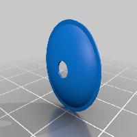
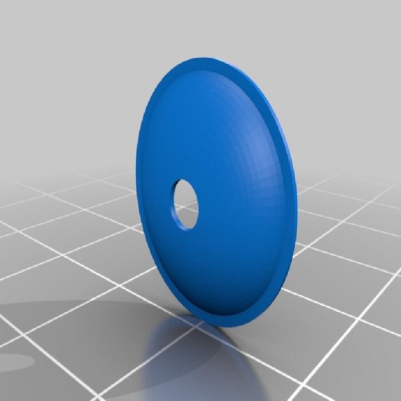
Glue together the two bottom parts, push them in the bottom part of the body and rotate it. Don't glue the bottom to the body, when the battery runs out you can open the screwdrivier from here and charge it. Glue the top to the inner outer, insert and glue the button, glue the lens to the top making sure the led fits the little hole fine.
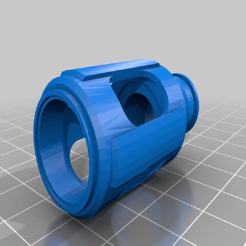
I added a microswitch in the inner sliding part, and carved along a line inside the body, so that the swtich is normally unclicked. The upper part of the notch gets thinner and thinner, to push down the switch button when the slider is fully extended, turning on the blue led inserted in the lens. I used a standard 12.8mm x 5.8mm microswitch
I chose a small (100 mAh) lipo cell which fits perfectly to get the most out of the small free space inside the body, you can find them on eBay. If you want to use coin batteries you'll have to edit the circuit and / or stl files by yourself. The light is a standard 3 mm 3000 mcd blue led.
The circuit is very simple: Battery cathode -> swtich Normally Open pin, switch common pin -> 30 ohm resistor -> led cathode, led anode -> battery anode
I chose a 30 ohm resistor because, due some voltage/current tests with this led, it makes it shiny enough without drawing too much current (the actual I/V value changes as the lipo cell voltage drops from 4.2 to about 3.5 volts (and so the voltage on the current limiting resistor drops too), so you can see 30 ohms as a compromise, not too much current when the battery is charged, not too low when it is nearly discharged
The bottom part is attached to the body thorugh a joint, so that you can open the screwdriver from there and recharge / replace the battery when it runs out