
Mr. Curtiss seems to be still bravely struggling with the difficulties of the new engine. He has been meeting with encouraging successes and exasperating delays, but it is obvious that as a result we are going to have finally an engine that will be worth something to the art of Aviation. An engine that will not break down in five or ten minutes and leave the aviator stranded…
He is apparently finding out the weak points of every part of the apparatus in turn; and at last when every difficulty seems to have been conquered and the engine is installed upon the Loon [hydroplane]… the cylinder blows its head off into the air.
Letter from Alexander Graham Bell, 3 December, 1908.
….
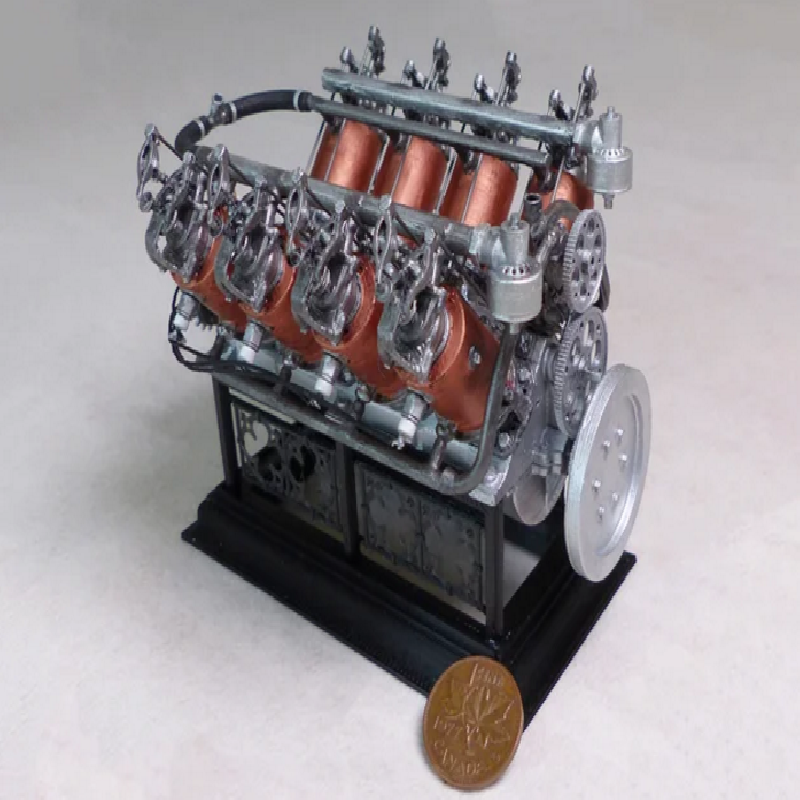
This model is a 1/8 scale recreation of an important early aircraft engine. It is based on a scan of an original artifact (Artifact no. 1967.0512.001) at the Canada Aviation and Space Museum, but it features a number of recreated elements now missing from the surviving engine. It is meant to be printed in FDM or SLA and assembled using CA glue.
The Curtiss “Number 3” was an ambitious experimental V-8 engine from the early days of powered flight. Conceived by the Aerial Experiment Association (AEA), a group of Canadian and American experimenters led by Alexander Graham Bell (1847-1922), it was meant to power an aircraft for longer distances, and with heavier payloads, than previous designs. It featured a cooling system that circulated water through thin copper jackets surrounding the cylinders.
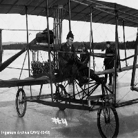
This engine was used in several experimental craft, but it is best remembered for powering the Silver Dart aircraft on its famous flight from the frozen surface of Baddeck Bay, in central Cape Breton, Nova Scotia on February 23rd, 1909. This is celebrated in Canada as the first powered flight (i.e. powered, controlled, and documented) anywhere in what was then the British Empire. The image of the fragile aircraft flying above the winter landscape is familiar to many Canadians.
The engine itself was a disappointment. Plagued from the start with reliability issues, it rarely achieved its rated power and was in constant need of repair. As other teams in the United States and France were achieving ever longer and more reliable flights, the AEA group struggled to get their engine into reliable operation. After the dissolution of the AEA partnership on March 31st, 1909, the engine’s Canadian owners replaced it with an automobile engine as they continued their experimental work.
Nevertheless, the engine was as a necessary link in a chain of technological experimentation that produced many generations of successful engines. Glenn Curtiss (1878-1930), the engine's New York-based maker, used this experience to refine his designs. On 28 Aug, 1909. Curtiss used his subsequent water-cooled V8 on his winning flight at the Rheims Aviation Meeting. A later V8 in this family, the OX-5, saw service during the First World War. By the 1920s, Curtiss was a world leader in powerful water cooled-engines. These included the Curtiss D-12 and its many successors and derivatives.
The Engine:
This process of development was taking place even while the engine was in service. In order to address its many problems, the engine was heavily modified over its short career. For this reason, it is difficult to describe the engine in anything but general terms without specifying a particular point in its development.
The “Number 3” is nominally rated at 50 horsepower at 16,000 RPM. The main casing is cast aluminum. The cylinders and pistons are cast iron, while the hollow crank shaft is of vanadium steel. Each cylinder is surrounded by a thin copper jacket through which cooling water is circulated using a single centrifugal pump. Ignition is by battery alone. The engine is lubricated by a “total loss” oil system fed from an overhead oil tank.
By the time that it was used in the famous flights of the Silver Dart, the engine's original configuration of one carburettor per cylinder had been replaced with a conventional cylinder and manifold arrangement for each cylinder bank. It had added a second pushrod-driven valve to replace the simple suction intake valves. The original two-belt drive system had been replaced with a chain-drive. This required the addition of a flywheel to the non-drive end of the motor. Perhaps for this reason, the distributor was shifted to the drive end. Many further changes were also made. When it left the workshop, the engine weighed 165 pounds (~75kg), but these subsequent modifications likely added substantial weight.
The engine’s ungainly appearance points to early challenges in developing inline aircraft engines. It was mechanically complicated and delicate. Many components are exposed that, in future V engines, would be encased in complex castings for protection, lightness, and rigidity. Among other issues, the engine was plagued by mechanical problems related to the complex cooling system.
This early V engine can be compared to the rotary engine design, which was first introduced in Paris in late 1908 at about the same time as the “Number 3”. The rotary was the first effective configuration for aircraft engines. Although it was crude and inefficient by later standards, the rotary principle of spinning the cylinder casings along with the propeller effectively solved the cooling problem while being reasonably reliable and very light.
If you would like some idea of what the operational “Number 3” might have looked and sounded like, there are a number of YouTube videos of its close relative, the Curtiss OX-5, in operation.
Artifact and Model
The Curtiss “Number 3” engine is on display at the Canada Aviation and Space Museum (CASM). The engine is unique. It is also in poor shape because it was recovered from the bottom of a lake after being used on a small fishing boat that sank. Many parts are missing, including most of the electrical, water cooling, and oil systems. In addition, aspects of the drivetrain were altered to adapt the engine to the boat.
The model is based on a 3d scan of the original artifact that was made at CASM on October 22nd of 2019 by members of the Ingenium conservation team. The polygon mesh generated through this process provided dimensional information for a parametric CAD model at 1/8 scale which was made using Autodesk Fusion 360 software. The original dimensions have been adjusted in order to be printable using a consumer-level FDM printer with a standard .5mm nozzle. The model has been separated into pieces in order to make it possible to print at this scale.
This is not a model of the artifact itself, but rather a representation of the engine as it appeared when it powered the Silver Dart during the historic flights in Nova Scotia in February of 1909. The model includes several elements, such as the gear-driven water pump and electrical system, which are missing on the surviving artifact. These aspects of the model have been reconstructed based on archival evidence. In some case, such as the gear-driven water pump, these features are barely visible in old photos. This recreation is, therefore, an educated guess. It may be updated when and if better evidence becomes available.
To make this model, you may need:
— Small hobby files, sand paper, and/ or emery boards for finishing the prints. These are useful for general finishing. Depending on the quality of the print, you may also need to trim parts, widen sockets, and sand back compressed first print layers.
— A hobby sprue cutter can help to remove supports, to clean up parts, and to trim them to fit.
— Cyanoacrylate glue (CA or Crazy glue) works well for gluing printed parts. I find it easiest to apply a drop to a piece of tin foil, and to use a toothpick to transfer a small amount to the model. The less you use, the faster it dries, the easier it is to work with. Once you have your piece set in place, you can add more glue to secure the bond.
— CA glue accelerator (“zip kicker”) makes assembly easier by speeding up drying time.
— Paint and primer. Start with a base coat of primer to ensure that the paint will adhere and spread properly. Mod Podge (or thinned PVA glue) is cheap, easy to apply, and works nicely on printed parts.
Assembling the model:
To begin, print out every part once, except the following:
Carb_FDM: Print twice.
Ironwork_FDM : If you want to embellish the stand, print this twice.
Cooling Pipe_FDM : This is included so that you can print replacement cooling pipes without reprinting an entire cylinder bank.
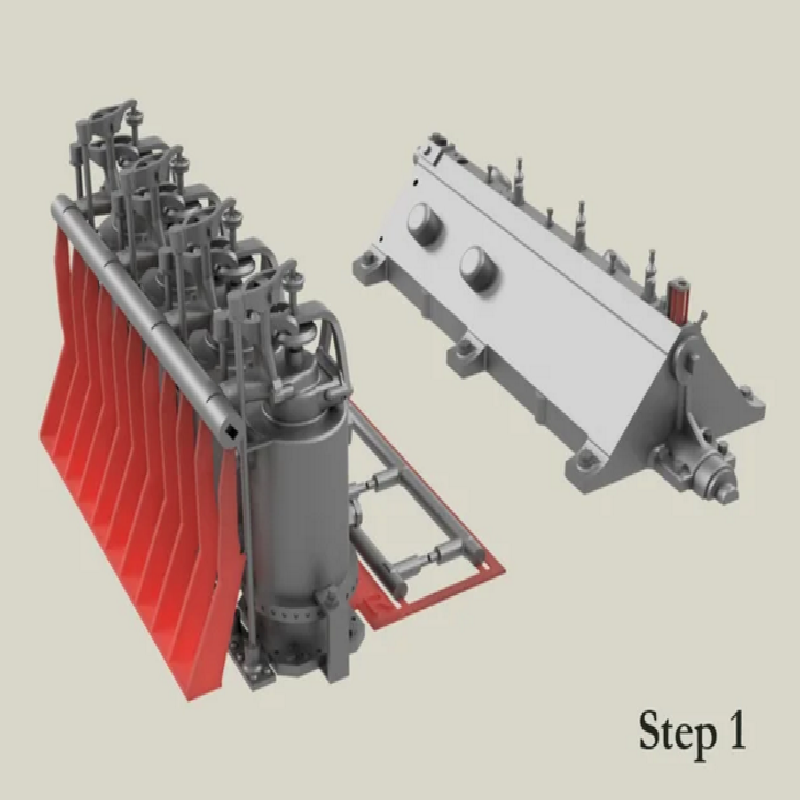
Step 1: Remove the supports indicated in red on each cylinder bank and on the upper part of the engine case. It is easiest to do this with a sprue cutter. Note that the supports are also attached to the centre of the valve push rods.
If you are painting the cylinders, or wish to replace the push rods (see below), it's easiest to do so at this point.
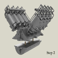
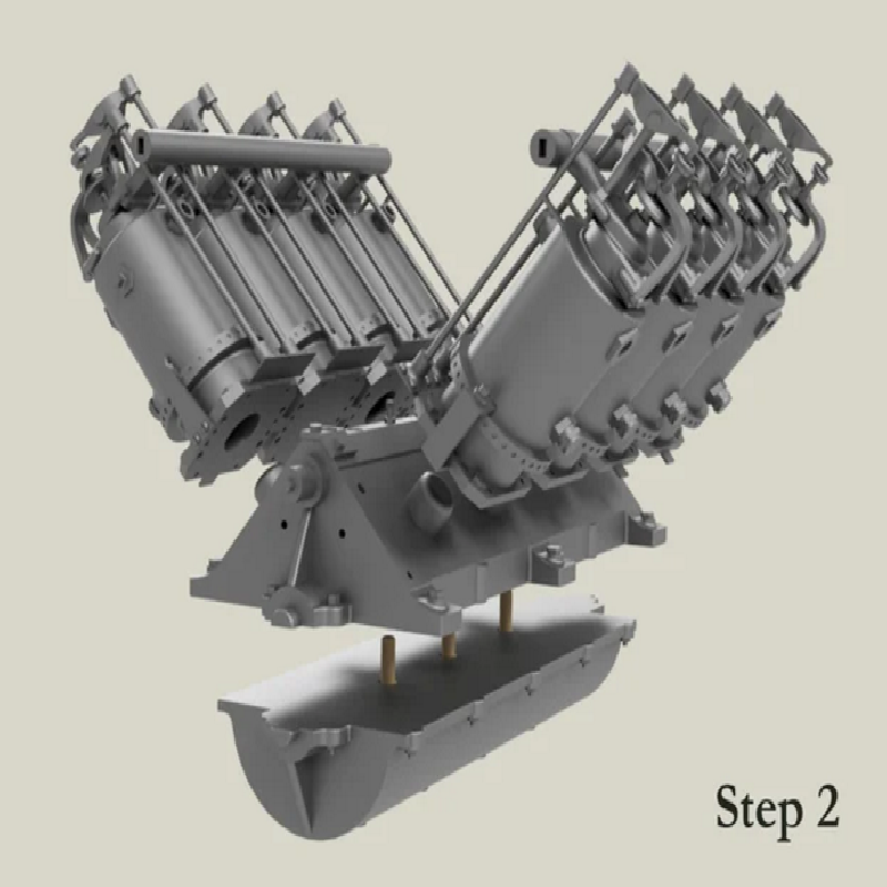
Step 2: Glue together the two-part engine case. To help with alignment, these pieces have channels that fit a length of round toothpick (2mm diameter).
Glue the left and right cylinder banks to the motor body. The guides on the top of the case will locate them on the correct side.
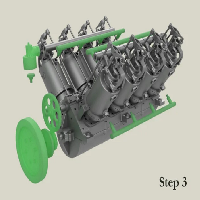
Step 3: Separate the water cooling channels, which were printed along with the cylinders, and glue the into the sockets on the two sides of each cylinder bank.
Each carburettor print consist of a main piece with a small hollow on the bottom where the attached smaller end is glued. You'll first need to separate these, and remove the little support under the collar where the carburettor meets the manifold on the cylinder bank.Glue one carburettor to each manifold. There will be a small indent on the correct side of the manifold that should fit the small pin on the end of the carburettor.
Glue the flywheel assembly to the boss on the same (non-drive) side of the model. The flywheel consists of the wheel itself and the flywheel mount piece. A circular channel at the centre of these pieces will fit a length of toothpick that will help you centre them together. Don't glue the toothpick into the pieces.
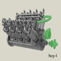
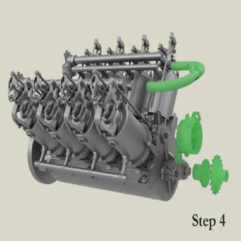
Step 4: On the opposite (drive) side of the engine, attach the two-part sprocket assembly. This is put together in the same way as the flywheel assembly.
Remove the two circular supports from the distributor. The socket on the back of the distributor fits onto the rectangular boss above the sprocket. The cylindrical protrusion (a ceramic insulator on an electrical connection to the batteries) should be facing upwards.
Glue the water outlet to the ends of the upper cooling pipes. The outlet has a small length of support at its centre that can be removed.
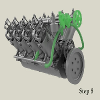
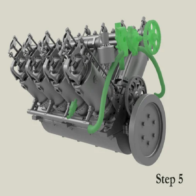
Step 5: Returning to the non-drive side, assemble the water pump. Remove the two small supports on the larger rear side. Align and glue together the two faces of the pump. Place the pump into the socket at the top of the engine case without gluing it. Place the pump gear into the front of the pump and orient the pump and gear at the correct height and distance so that the pump gear touches the timing gear, then glue the assembly into place. Finally, trim the supports from the left and right branches of the pump. Glue these into place so that they join the outlets of the pump to the lower water pipes.
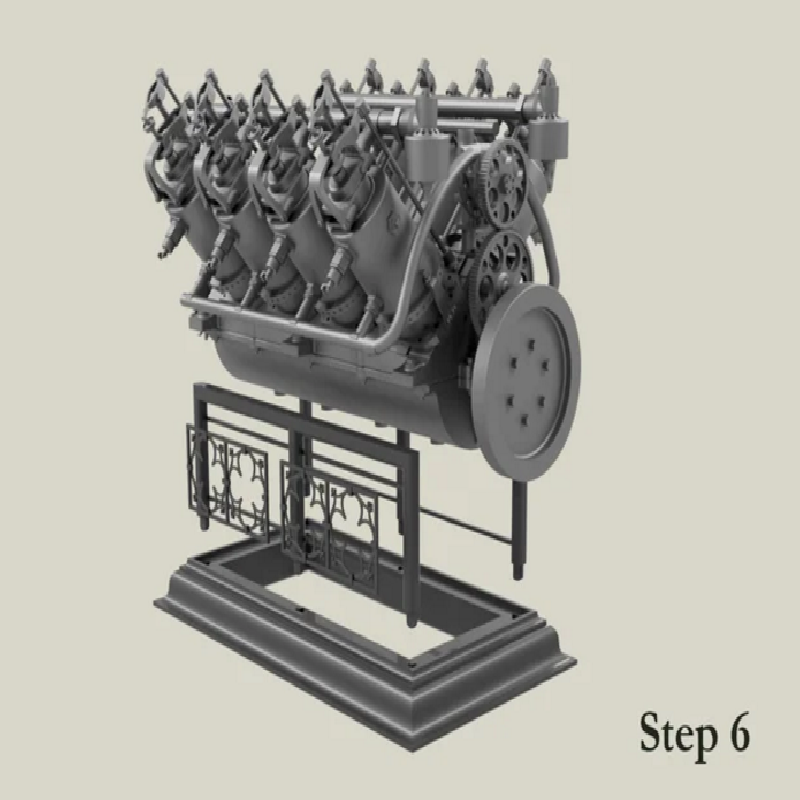
Step 6: Separate the sides of the stand and assemble it as shown. You can embellish the stand by trimming the iron work panels from their frame and gluing them into the horizontal bars on the stand sides. Otherwise, cut away the horizontal bars.
Post-Printing
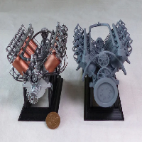
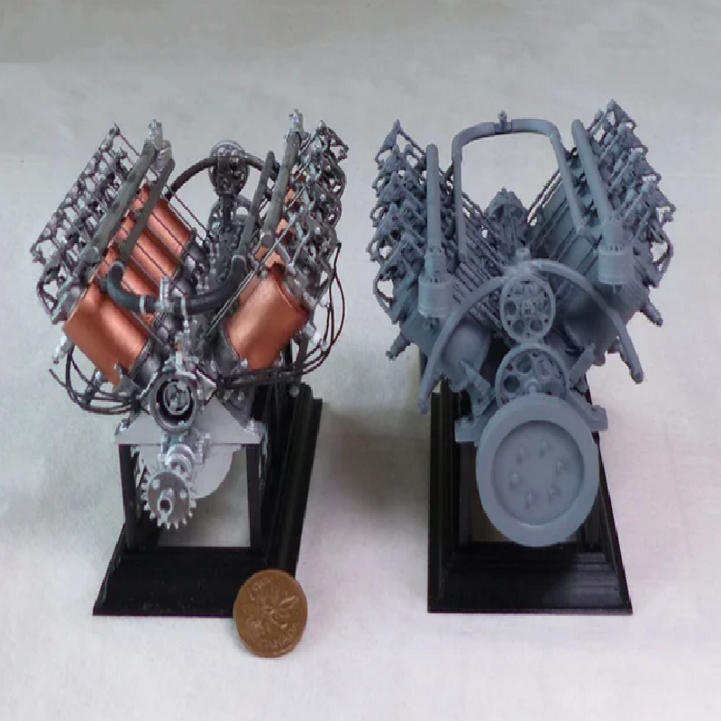
The second image above shows two models that have been built and finished to different standards. One, finished with model paint, uses both SLA and FDM-printed parts, and includes some scratch-built elements. The second is purely FDM printed with minimal finishing. It has been sprayed with grey all-purpose primer.
The "finished" model has the printed pushrods cut away and replaced with lengths of .6 mm metal rod bought at an art supply store. This is closer to the proper scaled dimensions than it is possible to produce with an FDM printer. It also represents the thick electrical cables running between the distributor and the spark plugs using cotton string. The string has been painted black and coated with PVA for stiffness.
There are many options for painting a convincing metallic finish, some more complicated than others. The key is to apply the metallic paint over a glossy black undercoat or primer.