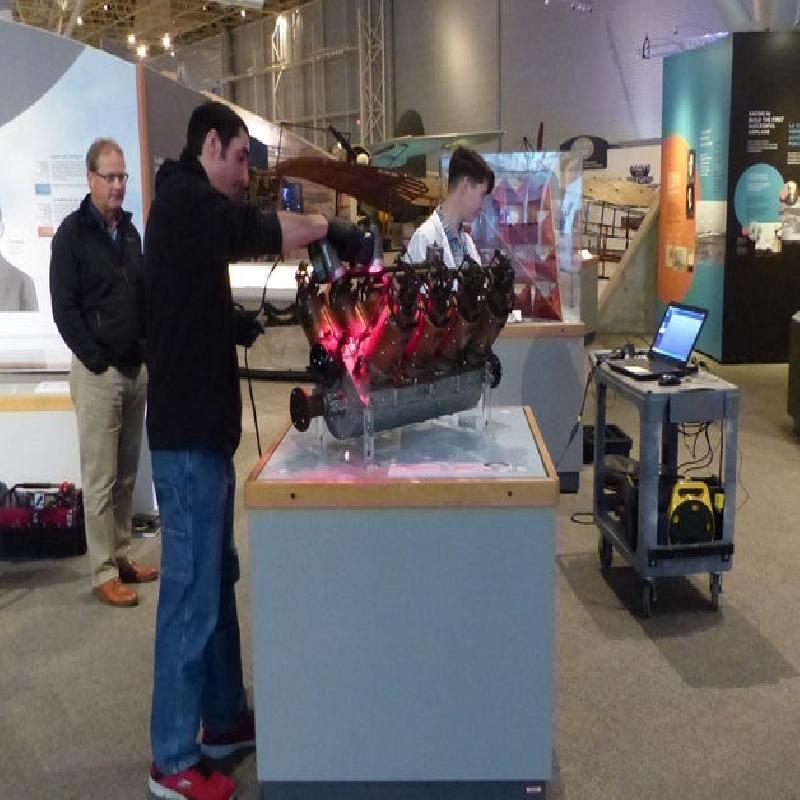

This model is based on a 3d scan of the historic Curtiss “Number 3” that is on display at the Canada Aviation and Space Museum (CASM). First run in 1908, this experimental engine powered the historic flights of the Silver Dart from the frozen surface of Baddeck Bay, in central Cape Breton Nova Scotia on the 23rd of February 1909. This was the first powered flight (powered, controlled, and documented) anywhere in the British Empire. The photographs of that delicate aircraft flying above the ice are iconic in Canada.
This engine is a less remembered part of that story, though it is an interesting piece of technology. After a short career as an aircraft engine, it was put on a small fishing boat, which later sank. The engine was later recovered in a damaged state, and put on museum display. This model represents a slightly “cleaned up” version of that artifact.
Experimental Aircraft:
The Curtiss “Number 3” is an early aircraft engine from near the beginning of powered flight. It was an experimental engine made in the workshop of Glenn Curtiss (1878-1930). It, and the various craft that it powered, were developed through a partnership called Aerial Experiment Association. This was a group of five individuals, led by Alexander Graham Bell (1847-1922) , that was dedicated to experimenting with the technology of flight. The partnership was sponsored by Bell’s wealthy and generous wife, Mabel Bell (1857 – 1923, née Mabel Gardiner Hubbard). For Curtiss, it was an opportunity to further his ambitions to enter the emerging aircraft market. His involvement permitted the Canadian group, led by Bell, to benefit from his workshop in Hammondsport, New York.
The Silver Dart was the group’s fourth aircraft. It was powered by the third engine used by the group, referred to in their correspondence as the “Curtiss number 3”. Both engine and aircraft were made and tested at Hammondsport before being shipped to Baddeck Bay, where the Canadians were located.
The engine was essentially a working prototype. It was delicate and unreliable. Aside from its early testing flights in New York, and its famous Canadian flights in February of 1909, it was frequently inoperable or severely underperforming. Curtiss, who was keen to apply this experience to developing new and better engines, was not particularly attentive to the concerns of the Nova Scotia group who struggled to make the engine work.
The engine's aeronautical career ended about two months after the famous winter flights of the Silver Dart when the Nova Scotia group ordered a replacement from Kirkham Motor Company of Bath, NY in late April 1909. This newer engine was used in the group’s demonstration flights for the Canadian Army at Petawawa, Ontario. During these trials, two aircraft, the Silver Dart and the Canadian-made Baddeck I, were wrecked, along with hopes that the Canadian government would sponsor further experimentation. By that time the Aerial Experiment Association had been dissolved, and the Canadian engineers had parted ways with Glenn Curtiss.
Meanwhile, Curtiss had attracted investment to establish a well-furnished aviation firm. On 28 Aug, 1909 Curtiss used a newer water-cooled V8 for his winning flight at the Rheims Aviation Meeting. This was a step towards the OX-5 engine that saw service during the First World War, and, beyond that, a long series of successful aircraft engines.
The Engine:
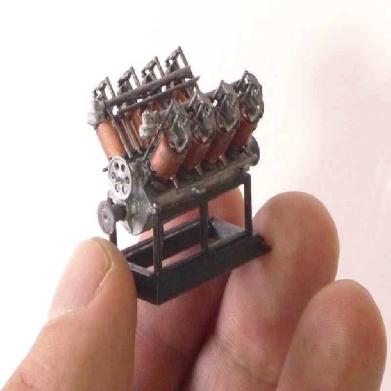
The engine is a water-cooled V-8 engine developing 50 horsepower at 16,000 RPM. The basic engine weighs 165 pounds (~75kg). The main casing is cast aluminum. The cylinders and pistons are cast iron. Each cylinder has a thin copper jacket through which cooling water is circulated using a single centrifugal pump. The engine was substantially modified over its short career. Its final configuration has two concentric valves at the top of each cylinder, one for intake, one for exhaust, actuated by long pushrods. Each cylinder bank is fed by a single carburettor and manifold.
This engine is unique. It is one of a series of experimental aircraft engines made in Glenn Curtiss’ workshop as he sought to develop a workable production model. Its appearance points to some of the early problems with inline aircraft engines. It was mechanically complicated and delicate. Many components are exposed that, in future inline designs, would be encased in complex castings for protection, lightness, and rigidity. The engine was plagued by cooling problems and mechanical challenges related to the complex cooling system.
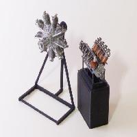
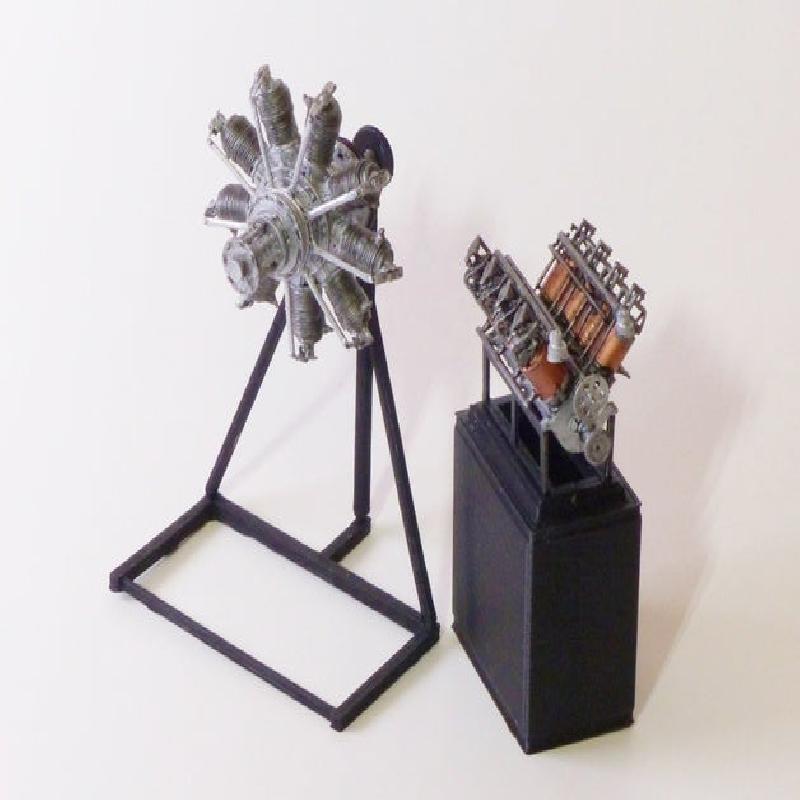
An interesting comparison can be made between this engine and the Gnome Monosoupape from 1916 which is modelled in the same scale here modelled in the same scale here. The Gnome’s basic rotary design was introduced in Paris in late 1908—roughly contemporary with the Curtiss. It was the first effective production aircraft engine. The rotary concept of spinning the engine body along with the propeller solved the cooling problems that plagued early aircraft engines. Compared to the Curtiss, the Gnome engines were also mechanically simpler and more reliable.
If you would like some idea of what this engine might have looked and sounded like when it was running, there are a number of YouTube videos of the Curtiss OX-5 in operation. The OX-5, also a water-cooled V8, is a close descendant of the number 3. It powered the Curtiss JN-4 Jenny training aircraft that saw service during the First World War.
There is little surviving documentation about the Curtiss number 3. It appears in a few archival photos, though details are hard to discern as the photographer's eye is usually directed elsewhere. If you are interested in researching this engine, you can join the conversation here:
The Model:
The model is based on a 3d scan of the surviving engine at the Canada Aviation and Space Museum using Fusion 360 software. The engine is damaged and incomplete due to its time underwater. It is missing oil lines, water lines, spark plugs, electrical wiring, a gear-driven water pump, and possibly other as-yet-unidentified elements. However, most of its basic elements are there.
This model represents a “cleaned up” version of that engine, meaning that damaged components such as the heavily corroded water pipes have been restored. In any case, the fragmentary corrosion of those parts would have been difficult or impossible to represent at this scale.
It may be possible through archival research to get a more complete picture of what the complete original engine looked like. If so, I may update this model to include representations of those missing parts.
This model has been designed to be printed at 1/25 scale so that it can be compared with a planned series of other engine models. At this scale, larger engines may still be represented at a reasonable size. This model is quite small, and may be challenging for inexperienced modellers. A larger 1/8 scale version will be published that will be easier to make.
This model has been designed for both SLA and FDM printing. Given the small size, some elements, such as the valve pushrods, have been made over-scale so that they can be reliably printed. Some parts have been made in two versions for either SLA or FDM printing. These have been given the suffix _FDM or _SLA.
To make this model, you will probably need:
Small hobby files or emery boards for finishing the prints. This is especially useful if your printer compresses the first layer.
CA glue. I find that cyanoacrylate works well for gluing printed parts. I find it easiest to apply a drop on a piece of tin foil, and to use a toothpick to transfer a small amount to the model. The less you use, the faster it dries, the easier it is to work with. Once you have your piece set in place, you can add more glue to secure the bond.
Tweezers. Some small parts, such as the valve timing gear, are easiest to handle with tweezers.
Primer, paint, small brushes: You have many options in terms of paints. Start with a base coat of primer to ensure that the paint will adhere and spread properly. Mod Podge (or thinned PVA glue) is cheap and works nicely on printed parts.
Assembling the model:
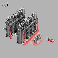
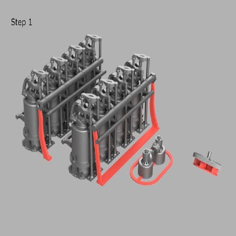
Step 1: Remove the parts indicated in red in the image above. This had been added to support overhanging parts or to ensure that smaller parts stick to the bed.
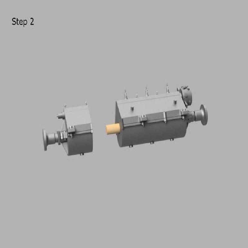
Step 2: Glue together the two-part main body. The body pieces have a channel that should fit a piece of round toothpick, which you'll have to cut to length. That will help you place them properly. If the bottom layers have been squished, file or sand them down where the two halves join. Don't sand away the small guides on the upper surface of the motor body as these will help you locate the cylinder banks on the correct sides.
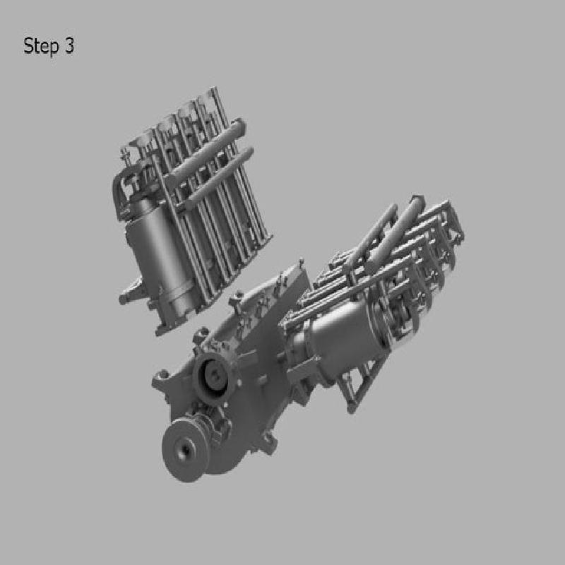
Step 3: Glue the cylinder banks to the motor body. If you are painting the model, it would be easiest to paint the cylinders and body separately before gluing them together.
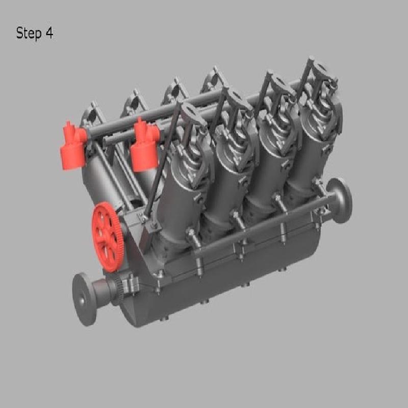
Step 4: Glue on the small pieces. Attach one carburettor to the end of the manifold on each cylinder bank. Glue the timing gear to its post above the crank.
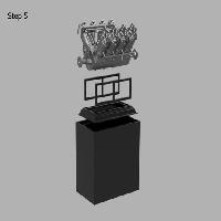
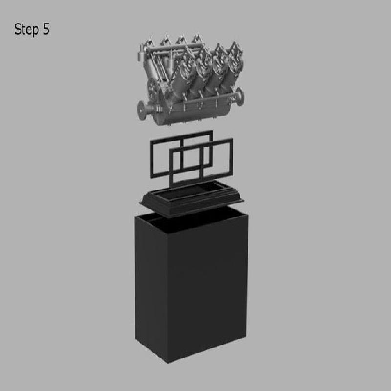
Step 5: Assemble the stand.
Printer Brand:
Prusa
Printer:
Rafts:
No
Supports:
No
Resolution:
.15
Filament: Doesn't matter. PLA
Notes:
This is FDM printable. Supports have been designed into the print. Slower printing is probably better with a very small and detailed model.
It should be easily printable with an SLA printer.