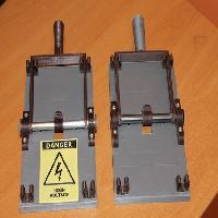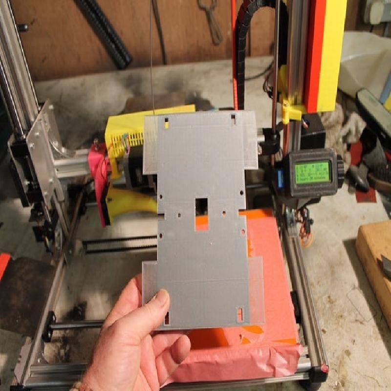

An OpenSCAD version of the classic Frankenstein Switch. Designed for a UK style rocker switch.
This is a cover for a switch to give it the appearance of an old "blade switch" often seen with sparks flying from it in old horror movies.
Most of these switches found on the internet are for American switches which are big toggle switches, not for the slimmer and smaller rocker style UK switches.
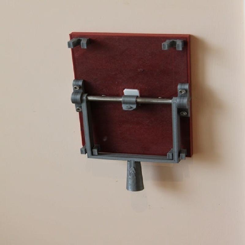
Fitting requires the removal of the two standard screws which hold the wall plate (i.e. the switch) in place. It DOES NOT involve removing the switch cover or messing with any of the electrics, but if you are not comfortable removing the mounting switches get someone who is to do the job for you.
In addition to the printed parts you will require: -
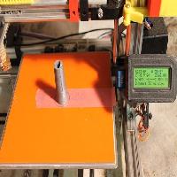
1 off 120mmx10mm (8-10mm will do) metal or wooden rod or tube. This version is for B&Q Varnished Cold-pressed steel Round tube (H)1mm (W)10mm (L)1m (https://www.diy.com/departments/varnished-cold-pressed-steel-round-tube-h-1mm-w-10mm-l-1m/254247_BQ.prd)
4 off M4 cheese head Allen screws & Nuts. (B&Q M4 Cylindrical set screw & nut (L) 16mm, Pack of 20)
Epoxy glue. (super glue sets too quickly for detail adjustments to be made)
Screwdriver and Allen key.
Printer Brand:
Velleman
Printer:
K8200
Rafts:
No
Supports:
Doesn't Matter
Resolution:
0.2
Infill:
20%
Filament: Masterspool Refills PLA 1.75MM Elefilament 3D Printer Filament × 1 Copper Mica PLA Copper and Silver
Notes:
Open SCAD & Print instructions & tips
If you need to modify the STL files (say you want to use a 9mm shaft) use OpenScad as follows.
There is one parametric OpenSCAD file which can output all the individual components. There is a "print" variable (on line 4 of the file). setting its value between 1 and 7 selects which part will be rendered.
Setting the value to 0 renders the entire finished switch, this is only for previewing the finished product, and is not used for 3D printing.
Setting the value to 8 prints a test piece for calibration.
1) Set the main_shaft_OD parameter in the file (line 17) to the diameter of your chosen shaft.
2) Set the print parameter to 3 and render a bearing. Output to STL ready for slicing and printing
3) Set the print parameter to 5 and render a knife rest. Output to STL ready for slicing and printing
4) Set the "print" parameter to 8 and render the test piece. This is used to calibrate the slots and holes that the above two pieces go in to.
5) 3D print one of each of the 3 above parts (preferably in one print run).
6) After printing check the fit of the bearing "leg" into the slot of the test piece and the knife rest "leg" into the rectangular hole. Also check the fit of the shaft you will be using in the shaft hole of the test piece.
Also check the fit of the M4 Cheese head screw in the bearing.
7) If required, adjust the parameter for locating_holes_tolerence to loosen or tighten the fit off the knife and bearing leg. If the leg fit is too tight increase the tolerance. if it’s too loose, reduce it.
Adjust the parameter main_shaft_OD to make the shaft a better fit. (if it’s too tight increase the diameter)
Adjust the parameter bearing_screw_cheesehead_dia and bearing_screw_cheesehead_height to ensure a comfortable fit in the bearing screw holes.
8) re-print ONLY the test piece to check that the modifications you just made are correct. Re-Adjust if required.
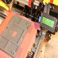
9) when you are happy with the fits, set the "print" parameter to 1 and render, then print the main base. Just in case you get warping I have added parameter use_hold_downs, set this to true to print custom "brims" to help hold down the corners, or just add brim to the slicer if your printer is big enough.
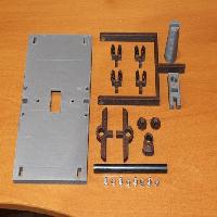
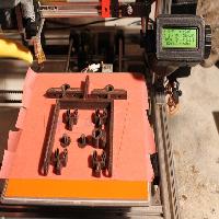
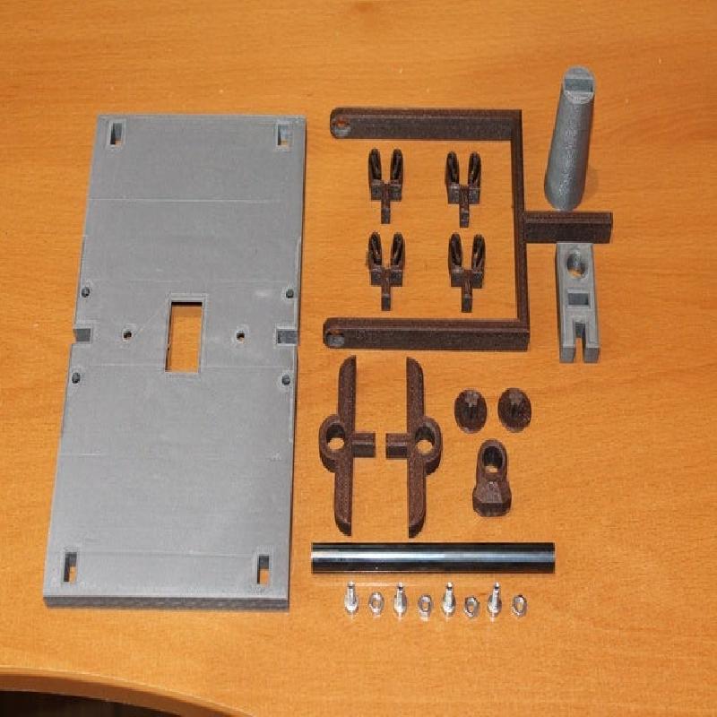
10) Set print parameter to each value from 2 to 7 in turn and render and save each output to suitably named STL file name.
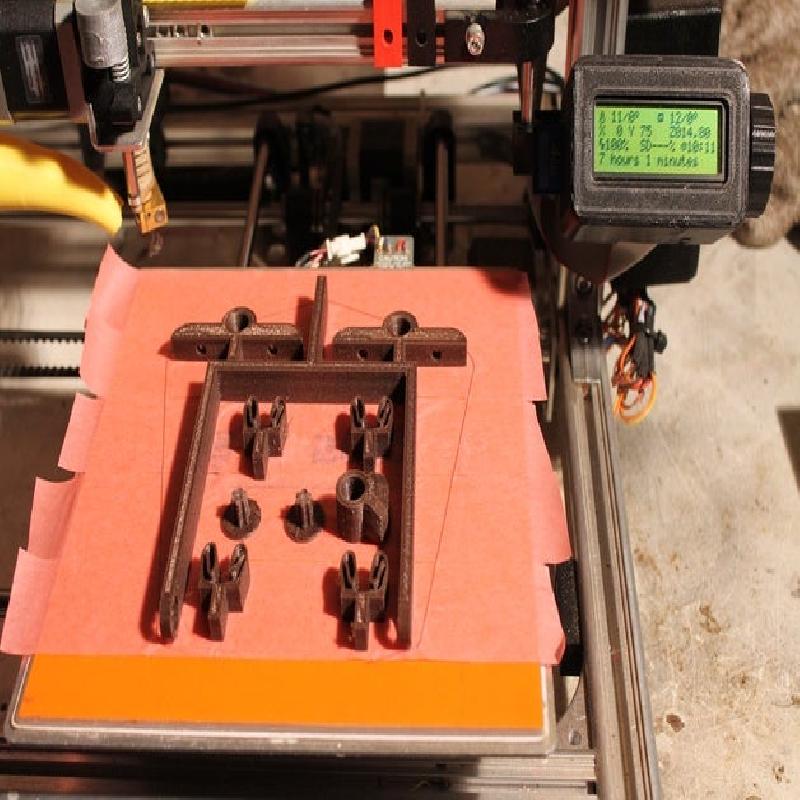
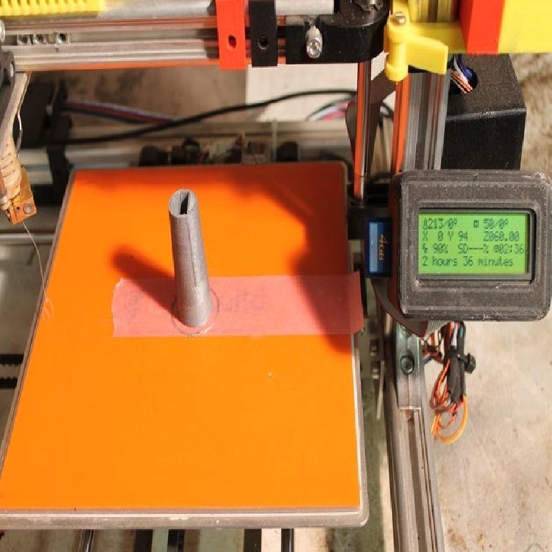
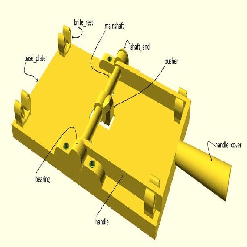
11) In a single print (not essential, but convenient) print 4 knife rests, 2 bearing, 1 handle, 1 pusher, 1 handle cover and if required 2 shaft end plugs (cosmetic if you are using a hollow tube for a shaft)
12) Check that the handle-cover slides over the handle. If it is too tight adjust handle_cover_Tolerence and re-render and print just the handle.
Build Instructions.
Build Instructions.
Ensure the shaft is exactly the width of the wall plate.
You may need to clean up the shaft holes in the handle, so that the shaft fits snugly but not so tight it strains the plastic. If need be, use a 10mm drill bit (or sized to match your shaft) to round them out. Do not put the bit in a drilling machine, just hold it in your hand to gently ream out the hole to the correct size.
Slide the shaft onto one side of the handle.
Slide on the pusher
Slide the shaft through to the opposite side of the handle.
Glue the pusher in place, in the middle of the shaft, with epoxy.
When pusher is set, slide onto each end of the shaft the bearings. This will position the handle in the correct place along the shaft. mark on the shaft wheel where the handle goes.
Remove the bearings.
Push the handle aside, so that you can apply epoxy glue there the handle goes, then slide the handle back into its marked location.
IMPORTANT: Rotate the shaft so that the pusher piece is directed towards the cross piece of the handle.
Clean away any glue that oozes out, pay particular attention to the side of the handle which abuts the bearing.
Allow the epoxy to set.
Re-insert the bearings on the shaft and Offer up the bearing feet into the locating holes.
Test install the M4 screws and nuts.
Drop the 4 knife rest feet into their holes, and check that the handle drops into them easily. The fit can be adjusted by dipping the knife rest in very hot water to soften them up, after which they can be tightened or loosened so that the fit on the handle is good.
When you are happy with the fit, glue the rests in place.
At this point you can test that the switch works by holding it over the real wall switch and operating the handle.
Now remove the bearing screws and remove the handle and shaft, ready for installation.
Fitting Instructions.
Remove the two screws on the "real" wall switch. Do not move the switch plate itself, it should stay in place by itself.
Offer up the Frankenstein wall plate to the real switch, ensuring that the 4 captive M4 nuts are correctly located in it. Re-insert the two switch screws. The screws should not need to be changed for longer ones as the plastic is only 2mm thick at this point.
Offer up the handle, shaft and bearings and screw into position with the 4 M4 screws.
If you have used a hollow shaft, then you can insert the end stops. (this is only cosmetic).