
by liftbag
This is a complete remix of the awesome Dual Mode Windup Car by Greg Zumwalt, which is no longer on thingiverse, but which you can find here: https://www.myminifactory.com/object/3d-print-dual-mode-windup-car-27061
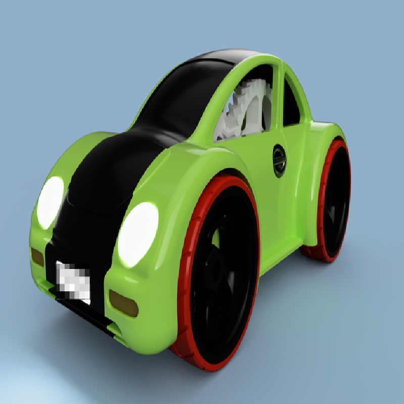
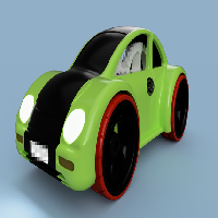
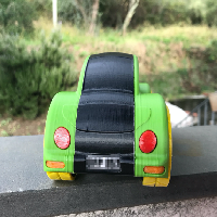
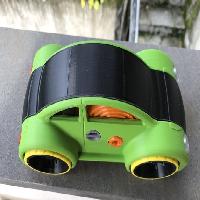
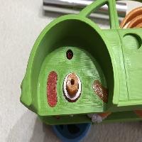
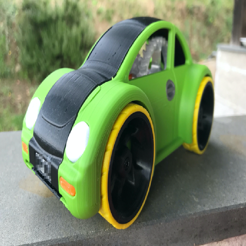
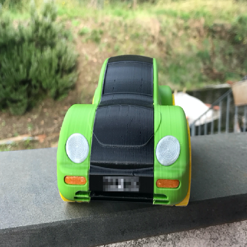
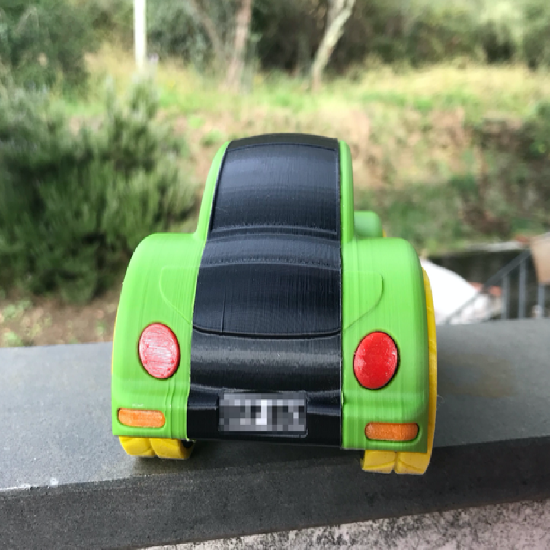
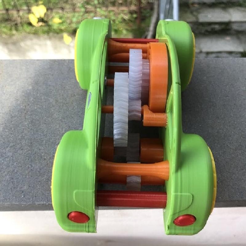
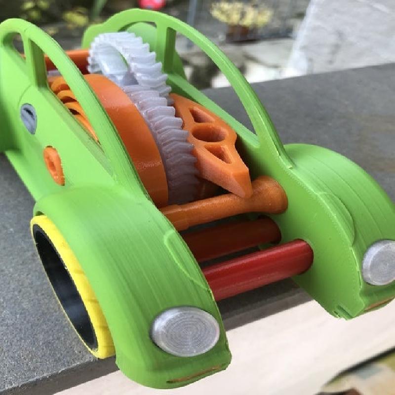
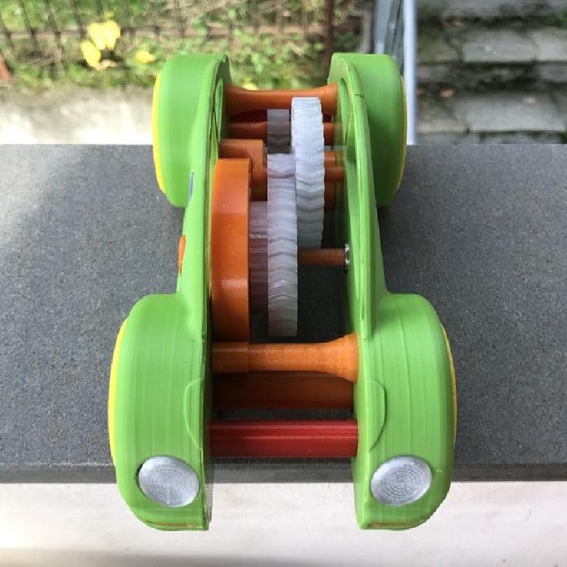
One of my childhood favorite toys was a model of Herbie, the love bug. So I wanted to draw a remix that reminded me of it, although later I followed the New Beetle design more closely.
Greg rightly notes in his comments that weight has a lot of influence on the performance of this toy. I noticed this with the first heavy prototype.
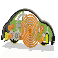
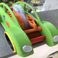
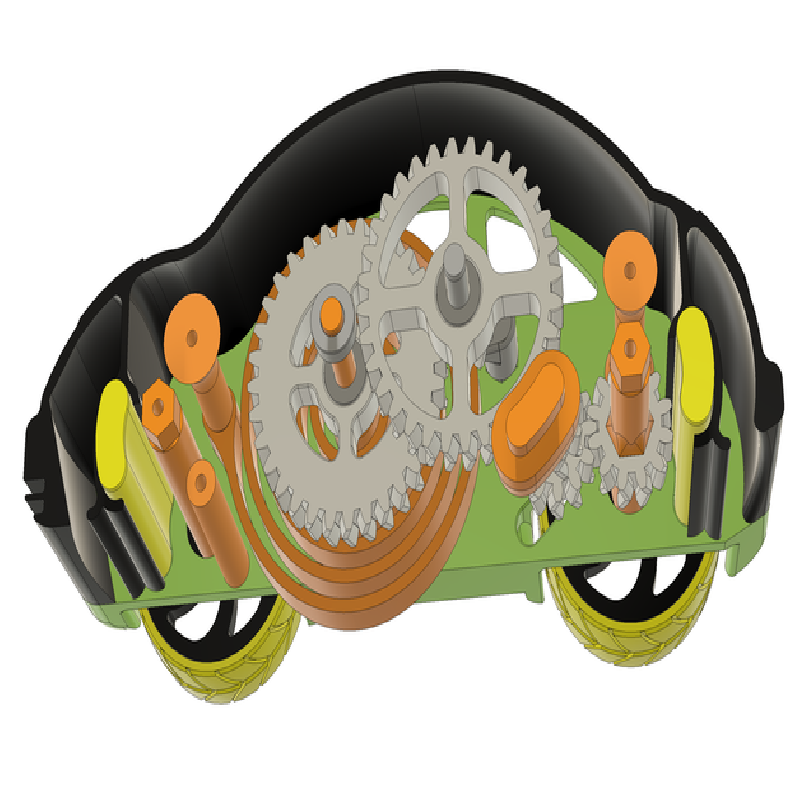
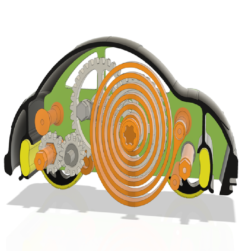
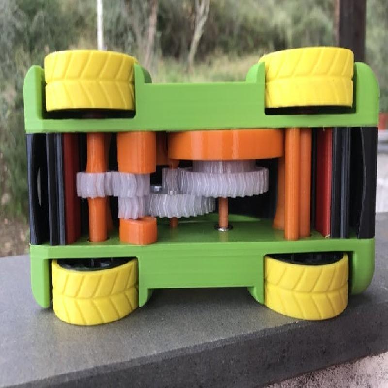
I then redesigned the gears set, enlarging them to accommodate a bigger and more powerful spring.
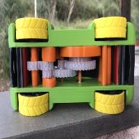
Initially, both for greater smoothness and to improve mechanical tolerances, I created a model that includes 10 ball bearings: no. 5 10x15x4mm (6700ZZ) and no.5 6x12x4mm (MR126ZZ). You can conveniently replace the latters by properly cutting Igus Iglidur 6x12 bushes as you can see in one of the attached pictures.
But I realized that the bearings on the wheel axles were not as sliding as the plastic bushings.
So, although the drawing remained the one to use the bearings, I designed bushings to eliminate the bearings.
To those who object that this increases the number of pieces and complications, I reply by saying that bushes wear out over time and that it is better to reprint simple bushes rather than a side body with worn holes. I get the best results by printing the bushings with PET, which is perhaps the best material also for printing the spring.
Another complication with respect to the original design is that it is necessary to thread several holes (M3), those on the wheel axles and those of the three spacers that hold the side bodies together. But thanks to these screwed spacers, a strict tolerance on cross members is no longer necessary.
To avoid collisions with the rims, M3 round head screws should be used in order to tighten the spacers to the body.
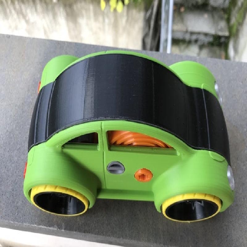
I designed a different rim, with a central locking screw: any M3 screw can be used to lock the rims to the axles.
For the tires I was inspired by John Corkery's remix, published here: https://www.thingiverse.com/thing:2140611. I designed the tire with a more curved profile, to reduce the footprint and reduce friction. Better to use a soft flexible filament to print the tires because the high initial power combined with the weight of the model could cause the tires to slip on very smooth surfaces.
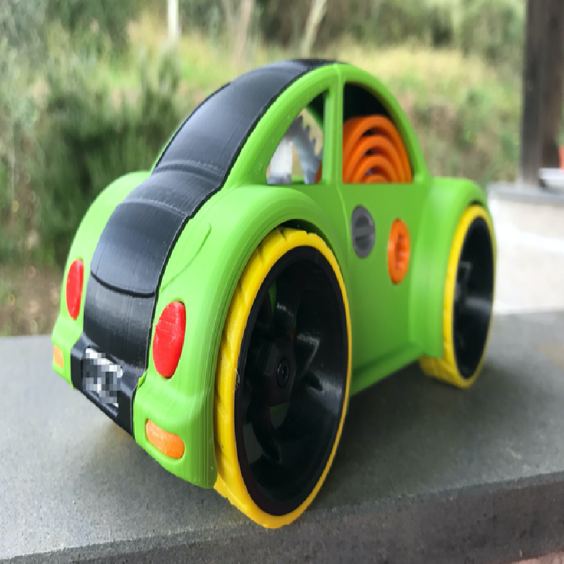
For those wondering what is the reason for the strange design of the recharge key, I did it to be able to insert it under the body top during transport, as seen in one of the attached photos.
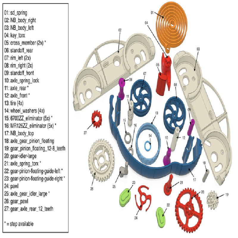
Finally, I included step files for all the elements you might want to change according to the output of your printer.
I did not count the hours needed to print the model, but we should be on time to have it ready for Christmas gifts.
Printer:
L200 (Lerdge powered M200)
Rafts:
No
Supports:
Yes
Resolution:
0.2
Notes:
Print the tires with Ninjaflex or Rubber HS or soft tpu.
Print the spring with PET or PC, use as many perimeters as is enough to make it full.
You can use PLA for the rest.
Pay particular attention to avoid the elephant foot on the gears first layers.
The lighter the model, the farther it will go, so use low infill where you can.

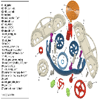
Install instruction
Install three 6700ZZ_eliminator_x_5.stl into NB_body_right.stl: front and real wheel axles holes and axle_spring_torx.stl hole. Alternatively, 6700ZZ ball bearings can be used.
Position axle_spring_torx.stl into NB_body_right.stl, then press sd-spring.stl and pawl.stl onto axle_spring_torx.stl.
Press one each of cross_member_x_2.stl into NB_body_right.stl at the front and rear.
Press gear-pinion-floating-guide-right.stl into NB_body_right.stl.
Tap M3 all the holes of axle_spring_lock.stl, standoff_rear.stl, standoff_front.stl, axle_front.stl and axle_rear.stl.
Lock the sd-spring.stl withaxle_spring_lock.stl, screwing the latter to the NB_body_right.stl with an M3x8 round head allen screw.
Lock in place standoff_rear.stl and standoff_front.stl as above step.
Press fit two MR126ZZ_eliminator_x_5.stl into gear_pawl.stl and one into gear-idler-large .stl. Alternatively, MR126ZZ ball bearings can be used.
Press the hexagonal side of axle_gear_idler_large.stl into the NB_body_right.stl, orienting the gear axis towards the axle_spring_torx.stl.
Match gear-idler-large .stl and gear_pawl.stl and let them slide their respective axes until gear_pawl.stl is in contact with the sd_spring.stl.
Press gear-pinion-floating-guide-left stl into NB_body_left.stl and install two 6700ZZ_eliminator_x_5.stl in the front and real wheel axles holes. Press fit one MR126ZZ_eliminator_x_5.stl into NB_body_left.stl on the axle_spring_torx.stl corresponding hole. The respective ball bearings can be used.
Press fit one MR126ZZ_eliminator_x_5.stl into gear_pinion_floating_12-8_teeth.stl. The respective ball bearing can be used. Then insert the axle_gear_pinion_floating.stl in the gear_pinion_floating_12-8_teeth.stl.
Press gear_axle_rear_12_teeth.stl onto axle_rear.stl. The axle_rear.stl is asymmetrical and the short part goes to the right. With this in mind, press the gear_axle_rear_12_teeth.stl onto axle_rear.stl by orienting the gear teeth as shown in the assembly.stl.
Position the rear axle assembly in NB_body_right.stl
.
Position the floating idler assembly in NB_body_right.stl.
Press NB_body_left.stl onto the body right assembly. When complete, the front and rear cross members must be flush with the outside surfaces of the body sides, and there should be 39mm distance between the inside surfaces of NB_body_right.stl and NB_body_left.stl. Close the assembly screwing three M3x8 round head allen screw onto standoff_front.stl, standoff_rear.stl and axle_spring_lock.stl.
Install the four tire_x_4.stl on the two rim_left_x_2.stl and the two rim_right_x_2.STL.
Slide two wheel_washers_x_4.stl on each side of the axle_rear.stl and complete the rear drivetrain screwing two of the assembled wheels (left and right).
Press axle_front.stl into the remaining assembled right wheel, slide one wheel_washers_x_4.stl, then slide the assembly into position from the NB_body_right.stl. Put the last wheel_washers_x_4.stl and press the remaining left wheel onto the axle assembly. Lock the wheels with M3x10 screws.
Attach NB_body_top.stl onto the front and rear cross_member_x_2 .stl.