
"The rotary engine, with its fixed crankshaft and rotating cylinders spewing exhaust and castor oil all over the airplane and pilot, is a horrifying device to those used to the modern piston engine airplane. However it was relatively low in specific weight, smooth running, and it did cool unless excessively cowled"
Samuel D. Heron, History of the Aircraft Piston Engine, 1961.
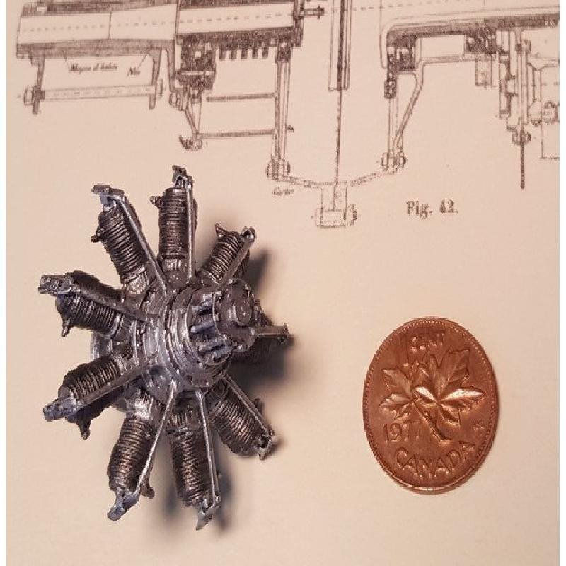
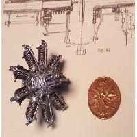
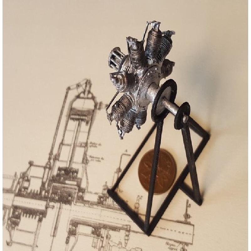
This a scale model of an important form of early aircraft engine. The nine-cylinder "Monosoupape" (French for "single valve") engine powered several allied fighters of the early war such as the Airco Dh-2 and the Sopwith Pup. Variants of this engine, and other French rotaries like the Le Rhône and Clerget, powered aircraft used by all of the major combatants in World War I. For instance, in the famous duel between the Sopwith Camel and the Fokker Dr.1 Triplane, both were powered by 9-cylinder rotaries, the former by a licence built Clerget, and the latter by a clone of the Le Rhône.
The four-stroke rotary concept was first developed into an efficient engine in 1908 by the French brothers Laurent and Louis Séguin who used effective machining techniques to produce an engine with a high power-to-weight ratio. These light mechanically simple designs could be used with airframes that were less massive, and consequently more nimble, than those of inline-powered aircraft.
In the rotaries, the propeller and cylinder block rotated around around a fixed shaft. The large rotating mass lost energy to air resistance ("windage"), and introduced gyroscopic forces that made it easier to turn in the direction of the engine's rotation.
The monosoupape model used a single valve for both exhaust and air intake. The valves were actuated by a pushrods geared to the engine's rotation. When the port was closed and the piston descended, gas was sucked into the cylinder through ports at the lower end of the cylinder. Castor oil, used as a lubricant, was consumed as it sprayed out of the spinning engine.
Unlike other rotaries, the Monosoupape reduced rotating mass by eliminating the carburettor, so there was no way to reduce the throttle by regulating fuel flow. The only way to regulate throttle was to cut the ignition, or, in later models, to selectively interrupt the ignition to a particular number of cylinders.
...
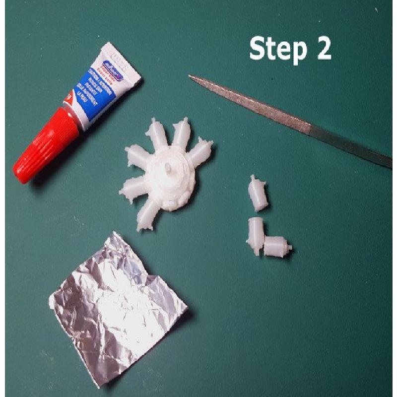
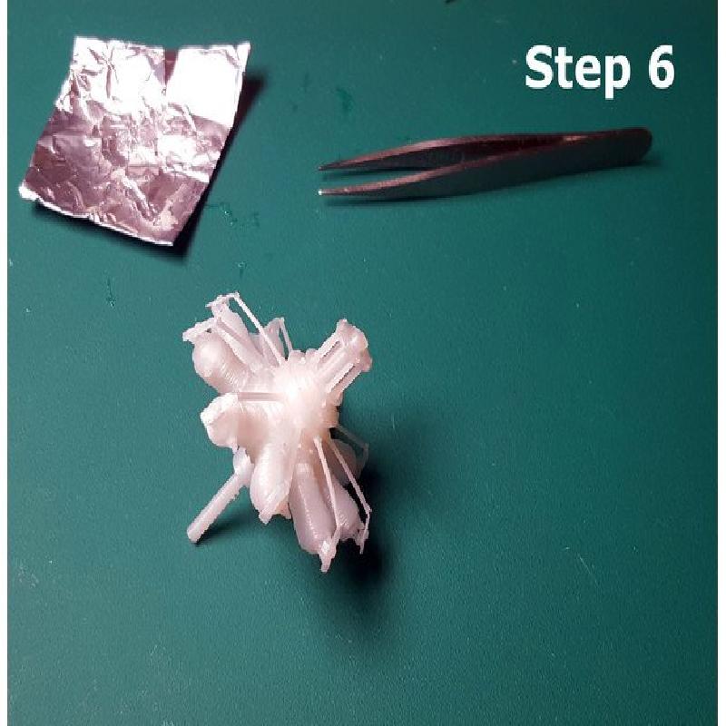
The model shows a number of the engine's key features, including the push rod and exhaust valve. It is assembled with CA glue. A cutting mat, sharp hobby knife, small tweezers, and small files would also be useful.
These files are meant to be printed on a "standard" FDM printer with a .5 nozzle. It is designed to as a 25:1 representation so that it can be compared to other areroengine models in the same scale. I'll publish more later. At a smaller scale, little engines like this would not be easily printable or makeable. At a larger scale, larger engines, such as later turbine engines, would be unreasonably big. You can scale this down if you have a narrower nozzle, or an SLA printer. If you scale it up, certain features, such as the bolts and pushrods, will probably seem overscale.
Instructions:
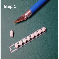
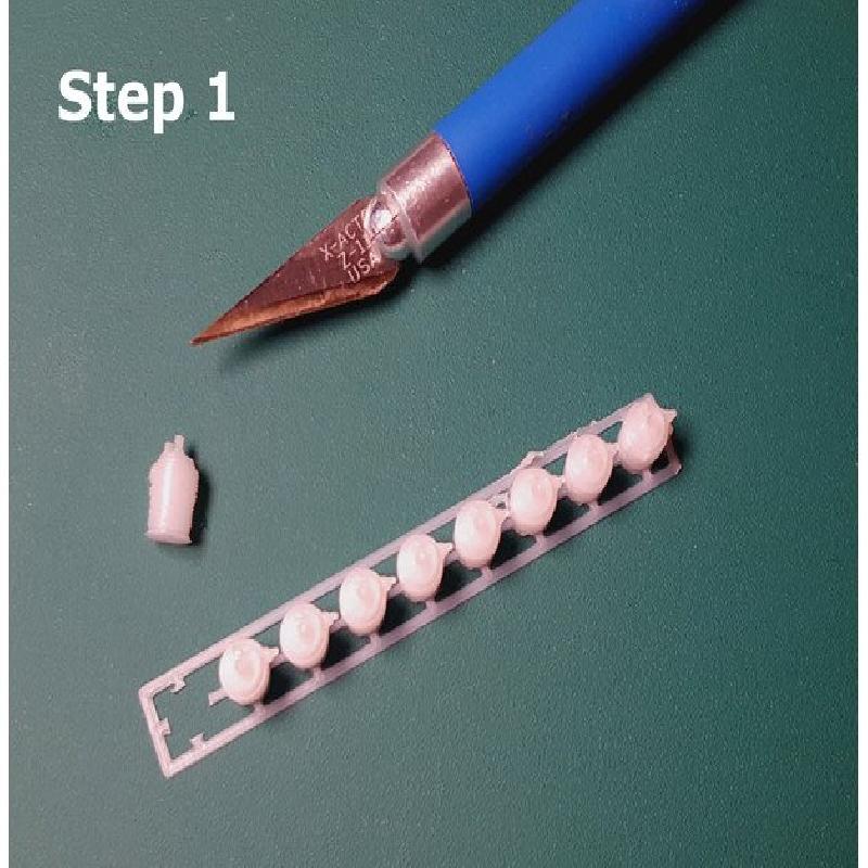
Step 1) The cylinders are printed as a group in order to prevent problems with bed adhesion. You can separate them by cutting the connections with a hobby knife. Each cylinder has a slot on the back to help position it properly on the centre body. Depending on how your machine extrudes the first layer, this might be narrowed slightly. Test the fit, and, if necessary, widen the slot with a small file.
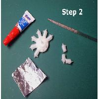
Step 2) Glue each cylinder to the centre body. You can dip it in a drop of CA glue on tin foil and press it into place. The spark plugs face left when viewed from the front.
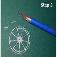
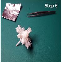
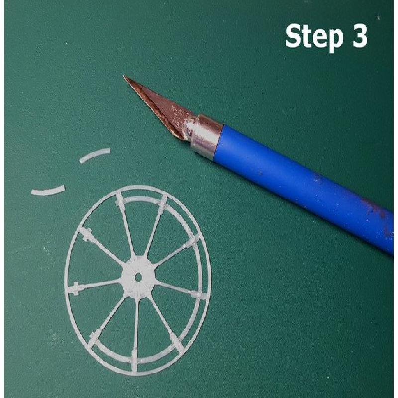
Step 3) Start preparing the push rods by placing the push rod disk on a cutting pad. The inner ring has a lower section on either side of the push rod. Cut the disk where the lower section meets the meets the raised section as shown in the photo.
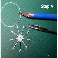
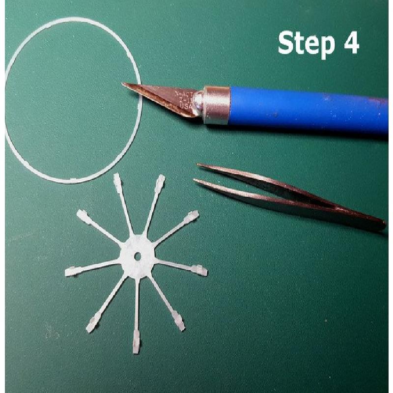
Step 3) The previous step will leave you with two little tabs on either side of the push rod. Using a tweezers, fold these downwards and squeeze them into place against the centre of the push rod. Using the tweezers, align them so that both tabs are parallel, pointing downwards. Cut each rod where it joins the outer ring. You should be left with something that looks like the photo.
Step 4) Glue the push rods onto the main body as shown so that each rod aligns with a valve at the top of the cylinder. Bend the end of the rod downwards and glue its end to the tip of the cylinder valve.
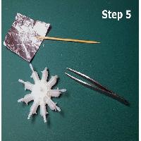
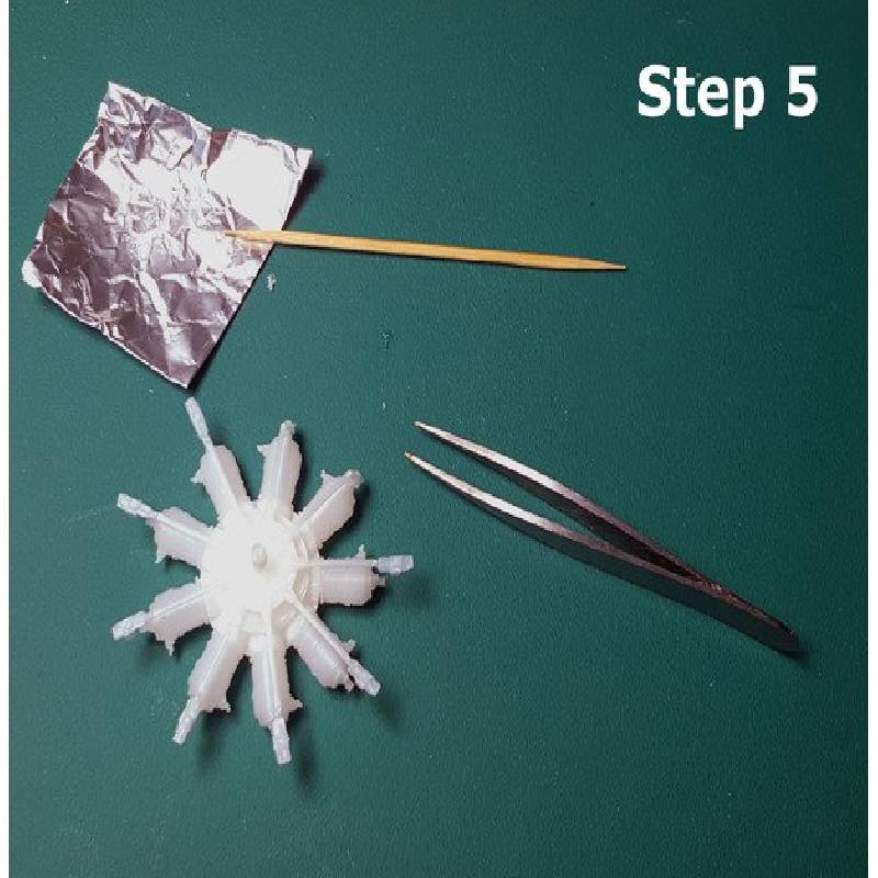
Step 5) Glue the top cap onto the push rod disk, and the back onto the opposite side. The back is composed of two parts that should separate fairly easily. If you glue it carefully, keeping the glue around the rim, the motor should rotate. Keep this part centred when you glue it to the back of the main of the main body. .
Finally, glue the hub onto the end of the drive shaft.
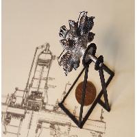
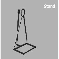
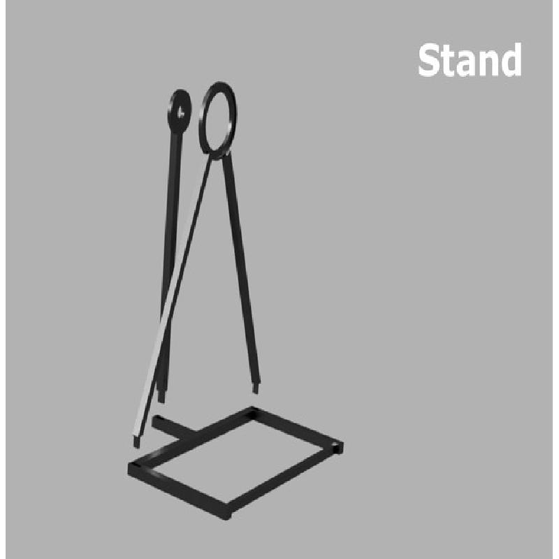
Stand: The stand comes together pretty easily, if you want to use it. Paint both the motor and the stand before gluing one to the other.
Printer Brand:
Prusa
Printer:
Rafts:
Doesn't Matter
Supports:
Doesn't Matter
Resolution:
.2 or smaller