
This is a remix of Reg Taylor’s wonderful Steampunk Grenade (https://www.myminifactory.com/object/3d-print-steampunk-grenade-3280). I took Reg’s suggestion and added some lights and sounds. Here is a list of parts that I purchased for this project:
2.54mm JST-XHP Connectors (https://smile.amazon.com/gp/product/B015Y6JOUG)
10mm Green LED (https://smile.amazon.com/Diffused-Green-10mm-LED-pack/dp/B076L2C8VF)
AAA Battery Terminals – 9.5x9mm (https://smile.amazon.com/gp/product/B07HRRV57Y)
5V Piezo Buzzer (https://smile.amazon.com/gp/product/B07GJSP68S)
Arduino Nano (https://smile.amazon.com/gp/product/B00SGMEH7G)
Adafruit 3.7V 400mAh Lithium battery (https://www.adafruit.com/product/3898)
JST PH 2-Pin Cable (https://www.adafruit.com/product/3814)
I also picked up an Adafruit Micro-Lipo Charger for the battery (https://www.adafruit.com/product/1904)
All the wire is 24 AWG stranded (https://smile.amazon.com/gp/product/B07DCV7BDD)
SWITCH BLOCK
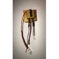
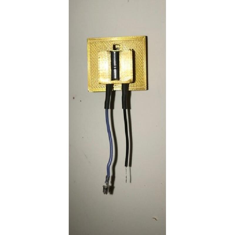
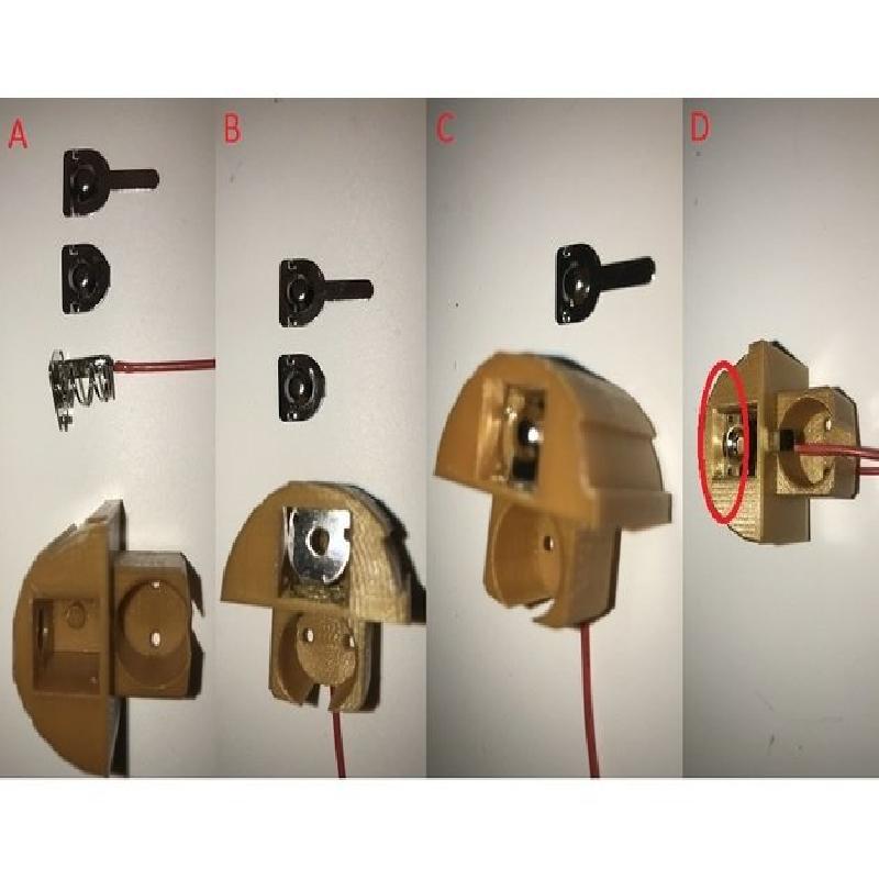
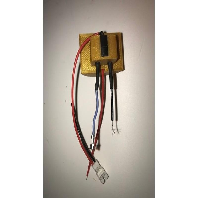
To assemble the switch block, start by soldering short pieces of wire, about 2 inches long each, to the piezo buzzer. Insert the piezo buzzer into the holder on the back of the switch block. Crimp a female JST pin to the positive wire and strip about 1/8 inch off the ground wire (image01). Next you will need two positive and one negative AAA battery terminal. Clip the tab off one of the positive battery terminals then solder a piece of wire about 3 inches long to the negative terminal. Bend the tab on the negative terminal 90 degrees up toward the spring (image02 A). Insert the wire and negative terminal into the switch block as shown, making sure the spring seats on the nub at the bottom of the space in the switch block (image02 B). Next take the positive terminal with the tab cut off and lay it on top of the negative terminal with the nub pointing up (image02 C). Finally, cut the red wire from the JST PH 2-Pin cable to a length of about 4 inches and solder it to the remaining positive terminal. Insert the wire and terminal tab through the slot at the back of the switch block just above the piezo buzzer (removed in this picture to make it easier to photograph). Push the terminal down until it is even with the slot in the front of the switch block and slide it forward into the slot (image02 D). This completes the assembly of the switch block (image03).
LED
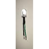
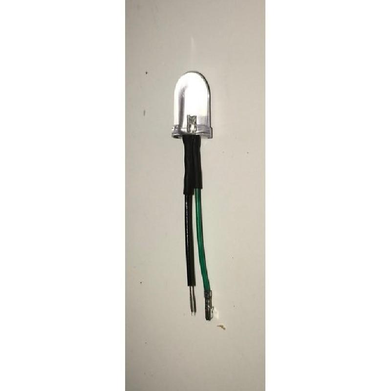
Solder two pieces of wire, about 2 inches long each, to the LED. Crimp a female JST pin to the positive wire and strop about 1/8 inch off the ground wire (image04).
ARDUINO NANO
From the included pin header block clip two pins off for the power connector and two pins off for the LED/Buzzer connector. Solder these on top of the board to the GND/VIN and the D8/D9 locations. Program the board using the included .ino file.
FINAL ASSEMBLY
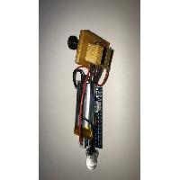
Cut one additional ground wire about 2 inches long. Strip about 1/8 inch off one end and crimp a female JST pin to the other end. Solder all four of the ground wires together and project with heat shrink tubing. Insert the red wire from the switch block and the ground wire into one 2-pin JST housing. Insert the positive wire from the piezo buzzer and the positive wire from the LED into another 2-pin JST housing. Connect the 2-pin JST connectors to the correct pin headers as shown (image05). Plug in the battery and LED should blink and the piezo buzzer should buzz. Insert the pin to ‘turn off’ the system. Paint the various pieces as you see fit. Glue the ‘Tubes’ to the ‘inner-part-1’ piece. Glue the ‘Cage-par-4 piece’ to the ‘inner-part-1’ piece. Glue the ‘detonator’ to the ‘Timer’ making sure the holes are aligned correctly.
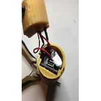
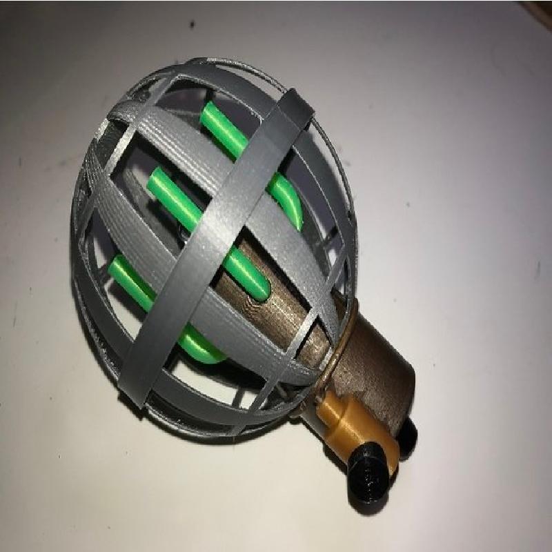
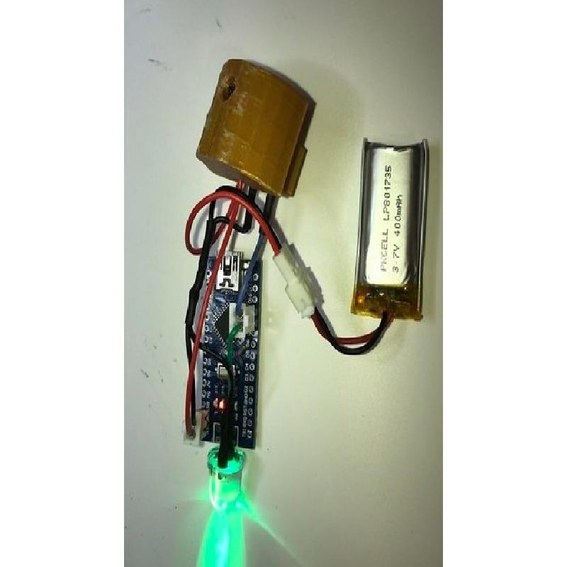
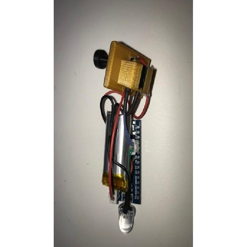
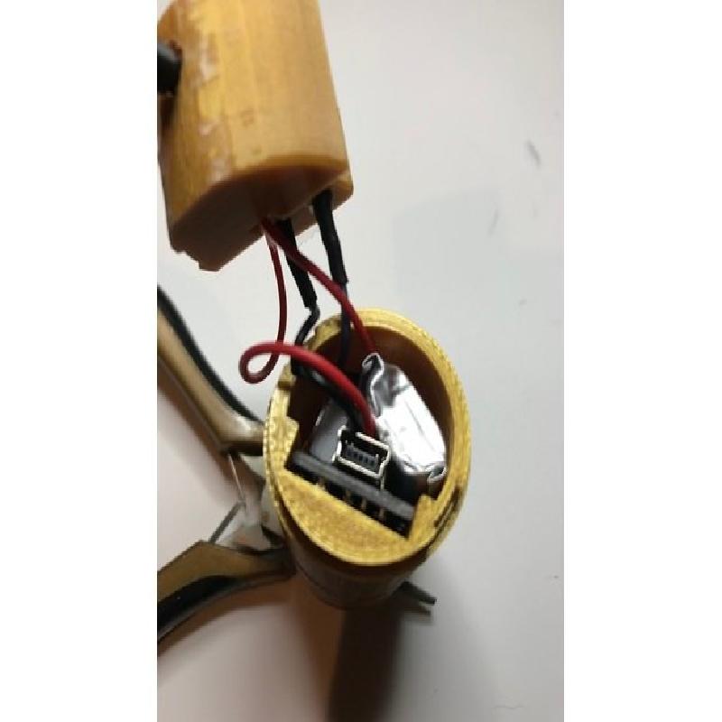
To get the whole thing packed into the ‘inner-part-1’ piece, place the battery on top of the Arduino board and press the wires into a bundle (image06). The carefully slide the whole package into the ‘inner-part-1’ piece as shown (image07). You may have to reach in with a probe to align the LED with the hole for everything to slide in easily. Push the switch block into the ‘Timer’ piece and make sure is seats correctly over the protruding square in the top of the ‘Timer’ piece. Align the tabs on the ‘Timer’ piece and attach it to the ‘inner-part-1’ assembly being careful not to pinch any of the wires. Assemble the rest of the grenade (image08, image09).
FINAL TESTING
Pull the pin and the LED should blink and the piezo buzzer should buzz at an increasing rate for about 12 seconds ending with a long buzz (https://youtu.be/_jNPchdFCa4).