
by Mafiatorte
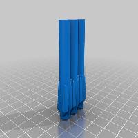
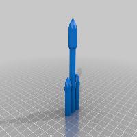
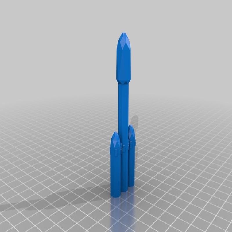
So this happens to be the remix, of the remix, of a remix. Originally created by Doctorwatson and modified by DAKINGINDANORF and metacollin. In fact, all I did with the parts was to scale them up to 126%
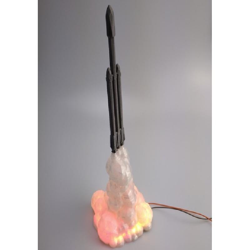
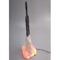
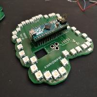
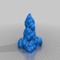
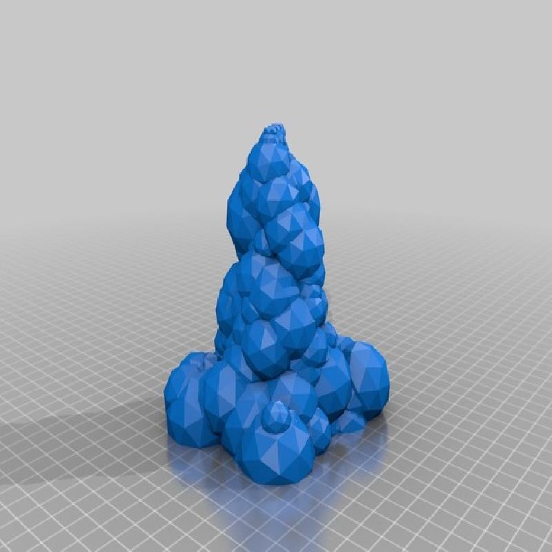
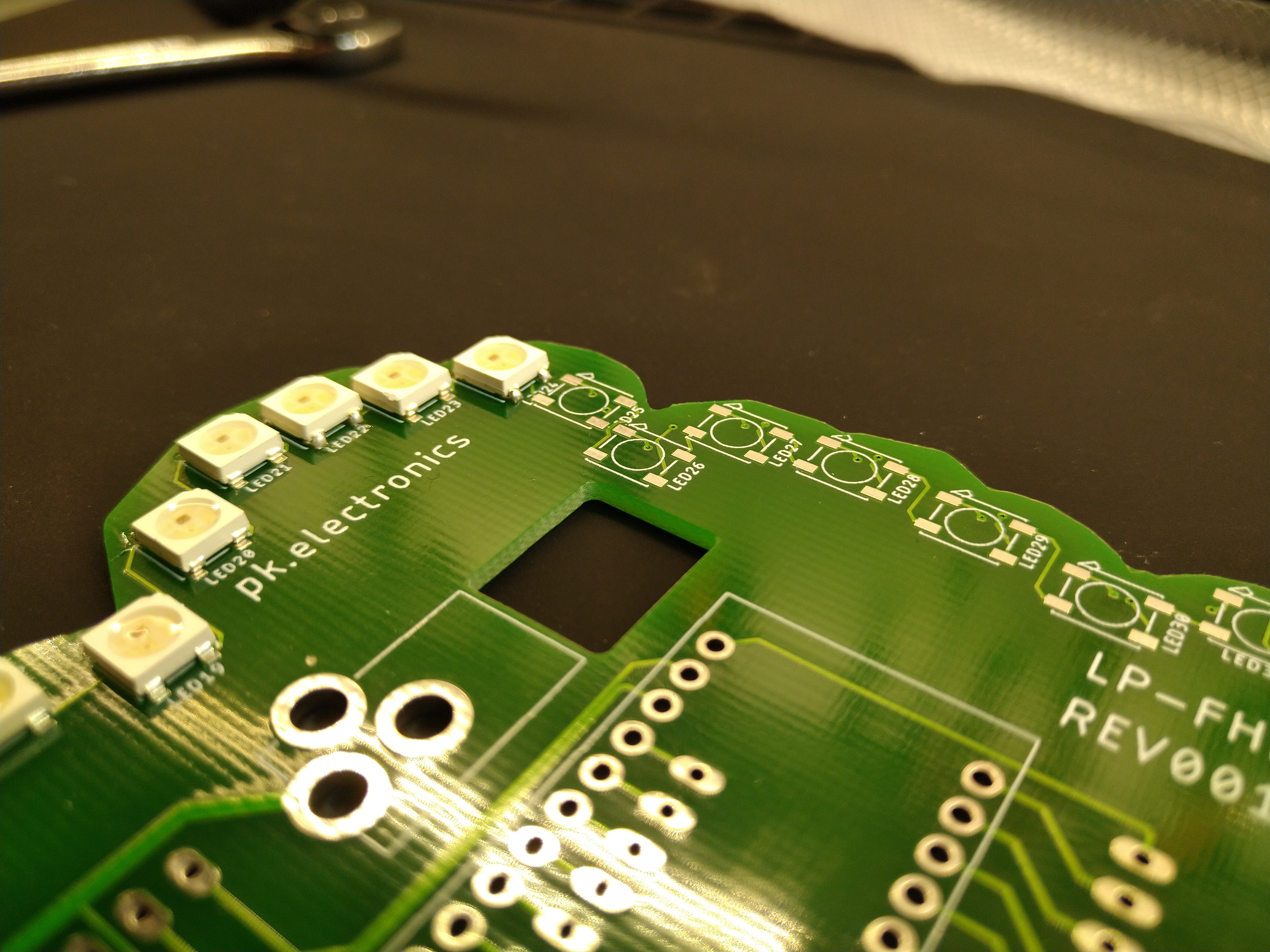
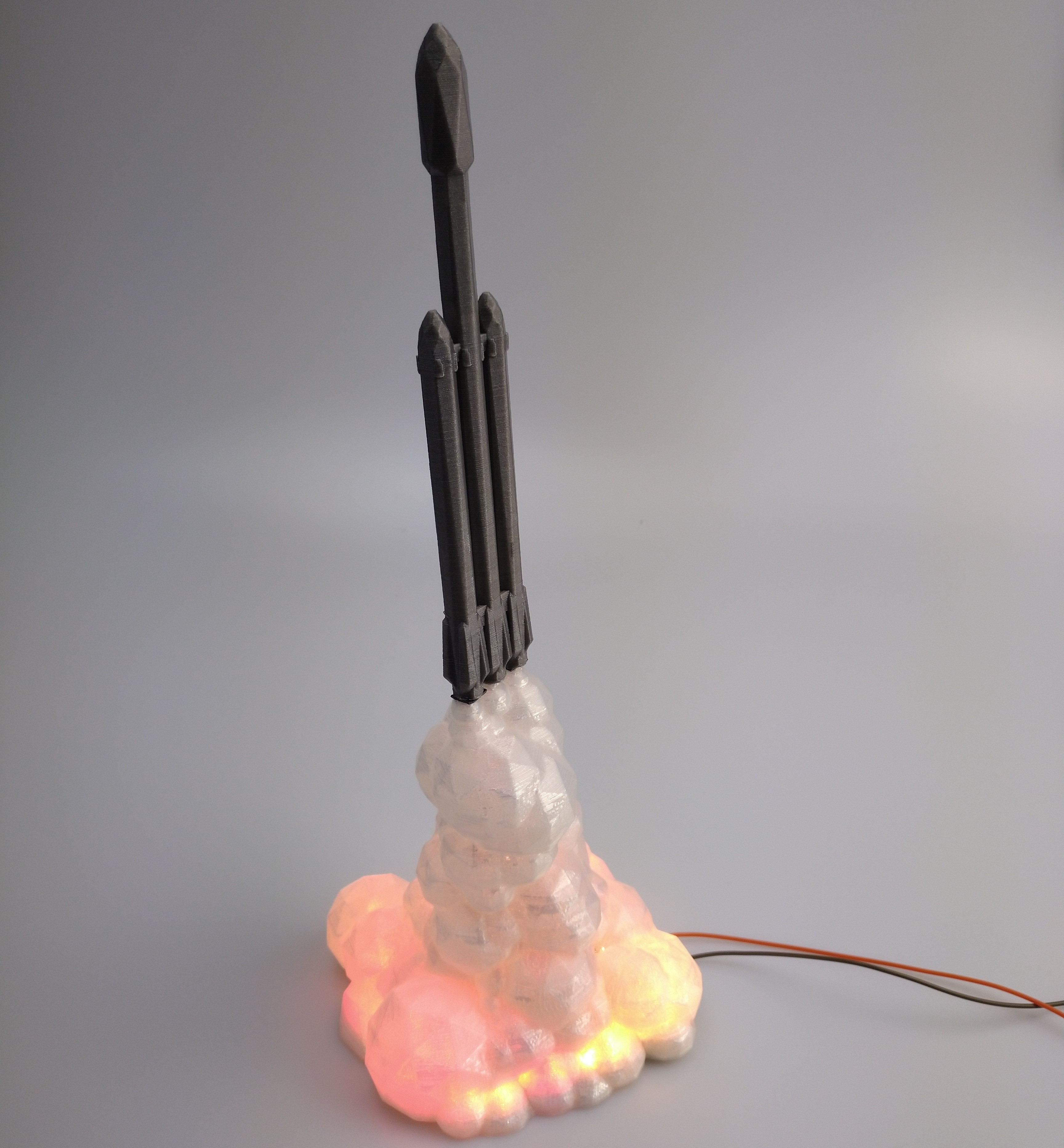
I decided to create a custom PCB which could fit just inside the hollow exhaust cloud to make an awesome piece for my desk. The PCB was designed using Fusion 360 and Eagle from Autodesk. It features 38 individually controllable rgb leds (WS2812b), an Arduino Micro and some expansion headers.
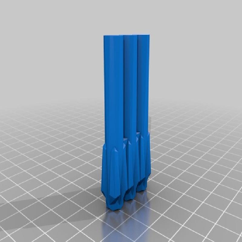
I won´t go into detail on how to print this part as my predecessors already done a great job doing so, but I´d recommend using some kind of opaque material for the base for obvious reasons.
Printer:
Tronxy X5-ST
Rafts:
Doesn't Matter
Supports:
Doesn't Matter
Resolution:
0.2 Layer, 0.4 Nozzle
Infill:
100%
Materials
PCBs
To start this project you´ll need to order your PCBs, I´d recommend doing so at JLCPCB.com as they offer satisfying quality for a really low price (e.g. you can get ten of the Falcon Heavy PCBs for less then 2$). Ordering the PCBs is really easy, just go to jlcpcb.com and upload the FalconHeavyPCB.zip by clicking the "Add your Gerber File" button. Then continue to checkout...
Leds
You will need 38 WS2812b Leds for each PCB, you can either order them from Adafruit (expensive) or from Banggood https://www.banggood.com/custlink/DmKmhH6sbe
Arduino Micro
I´d always recommend to buy an original Arduino Micro to support their initiative and to honour their contribution to the open source community.
5V Power Supply
The board draws about 450mA when all leds are white on full brightness, the PCB has mounting holes for a barrel jack but you could simply solder some wires to the pads if you desire. It doesn´t really matter as long as you supply exactly 5V to the board.
3D printed parts
I think this one is obvious :D
Tools
To assemble the PCB you´ll need the following tools.
Soldering Iron
Solder
Tweezer
Magnifying Glasses (optional)
Assembly
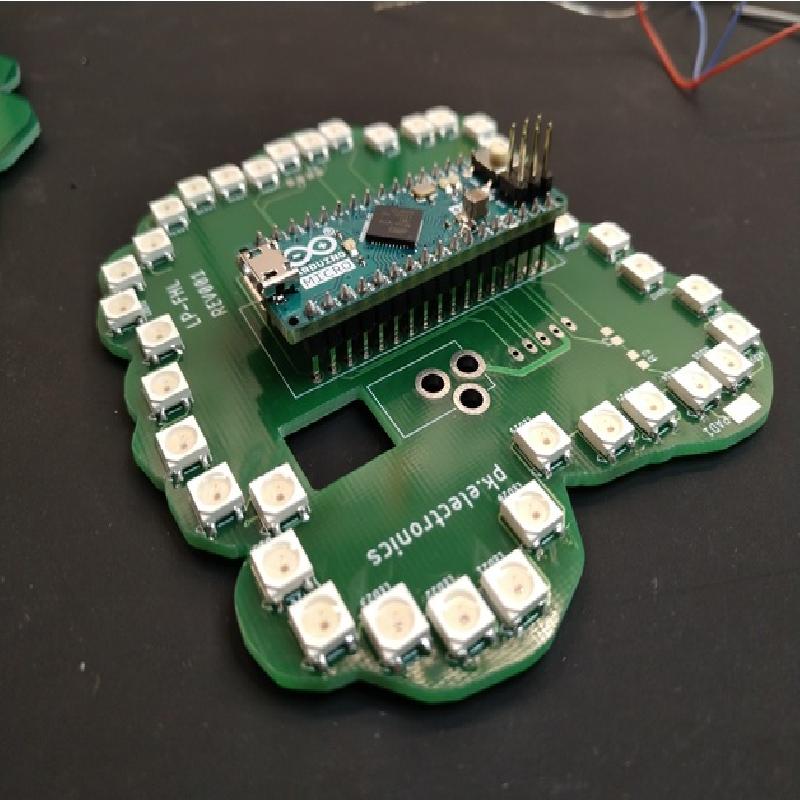
Start assembling the PCB with the leds, watch out for the correct orientation of each leds as not all have the same orientation.
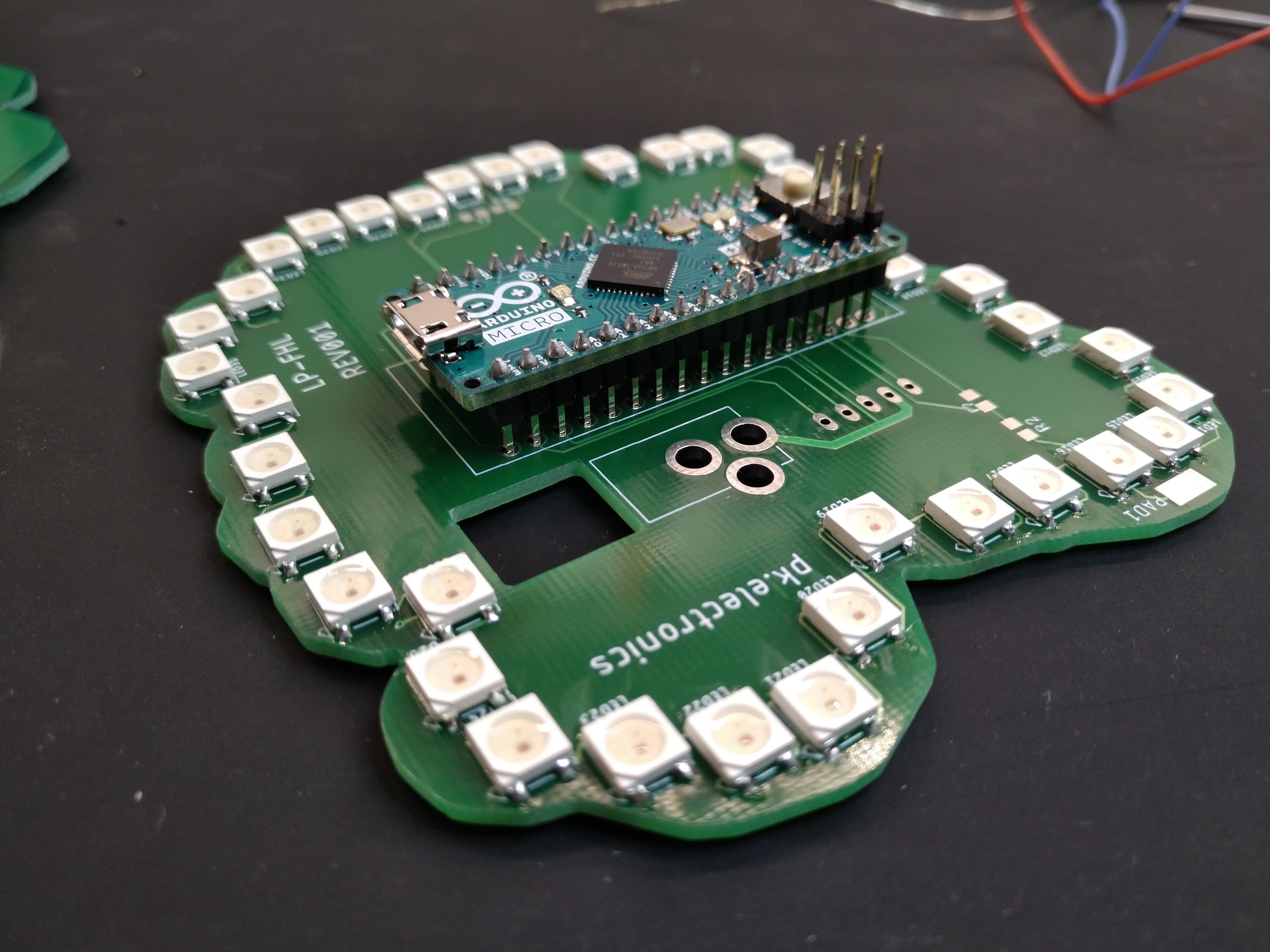
After that, insert the Arduino Micro into the holes as shown in the picture. Make sure it is oriented correctly, otherwise the whole board won´t work.
Software upload and first test
To create a flickering fire effect I took the jack-o-candle code created by github user schnoggo and modified it to my needs.
Attach the assembled PCB to your PC using a micro USB cable, then open the FalconHeavySketch.ino with the Arduino IDE, select "Arduino/Genuino Micro" in the Tools->Board menu and select the correct comport in the Tools->Port menu.
After that, hit "Upload".
Once the upload has finished the leds should start flickering.
If this is not the case, e.g. not all leds light up, you should check all leds for correct orientation and for bad soldering joints.
Finishing touch
After you successfully tested your led board, solder your powersupply to the corresponding pads, or insert the barrel jack into the connector. I added the cutout in the PCB for the sole purpose of running additional wires through it.
At last, you may also add some rubber feet to the bottom side of the PCB.
Once you´re done, gently push the PCB into the hollow exhaust part until it won´t fall out by itself, normally no adhesive should be necessary to keep it in place.
Last Words
If you want to modify the pcb send me a DM and I will give you the files. PCB design is licensed under the cc-by-nc-sa 4.0 license.
I case you want an assembled pcb, DM me as well and we will see what´s possible.
As you may have noticed, the boards have some additional pads for 0805 components and some exposed pads. These were intended to experiment with touch sensing, also known as QTouch, but I haven´t found time to do so and may add it later.