
by 3ddruckqueck, published
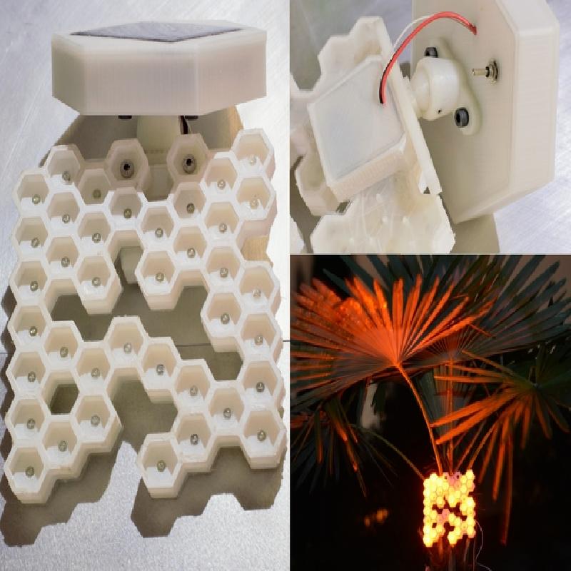
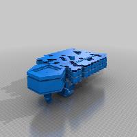
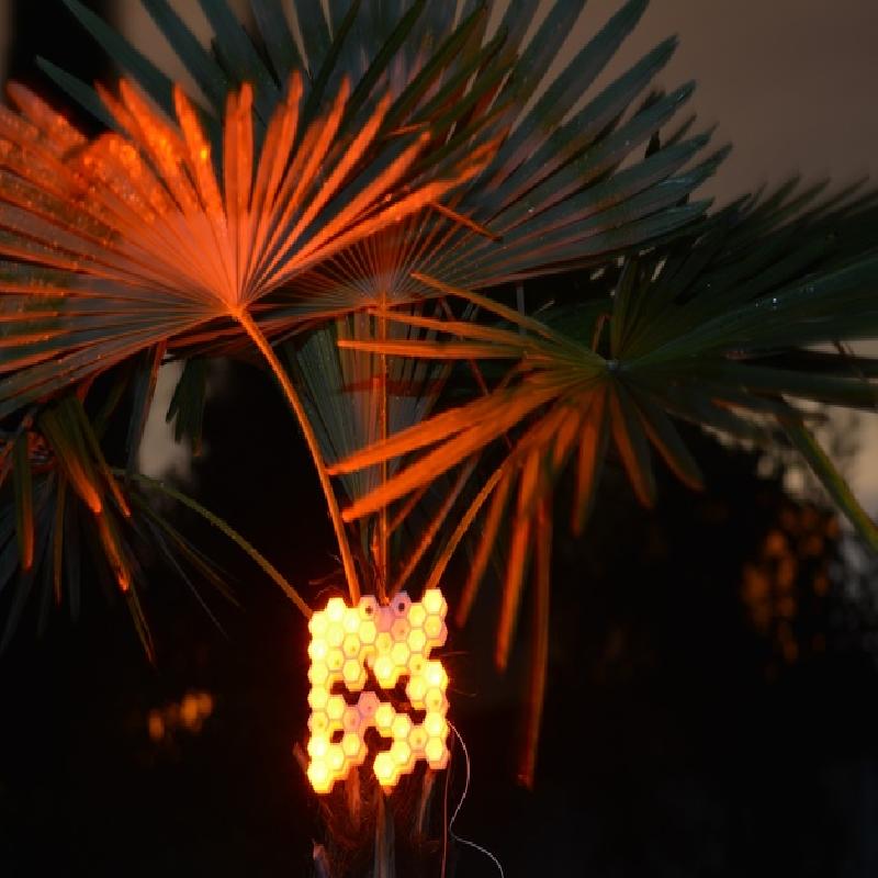
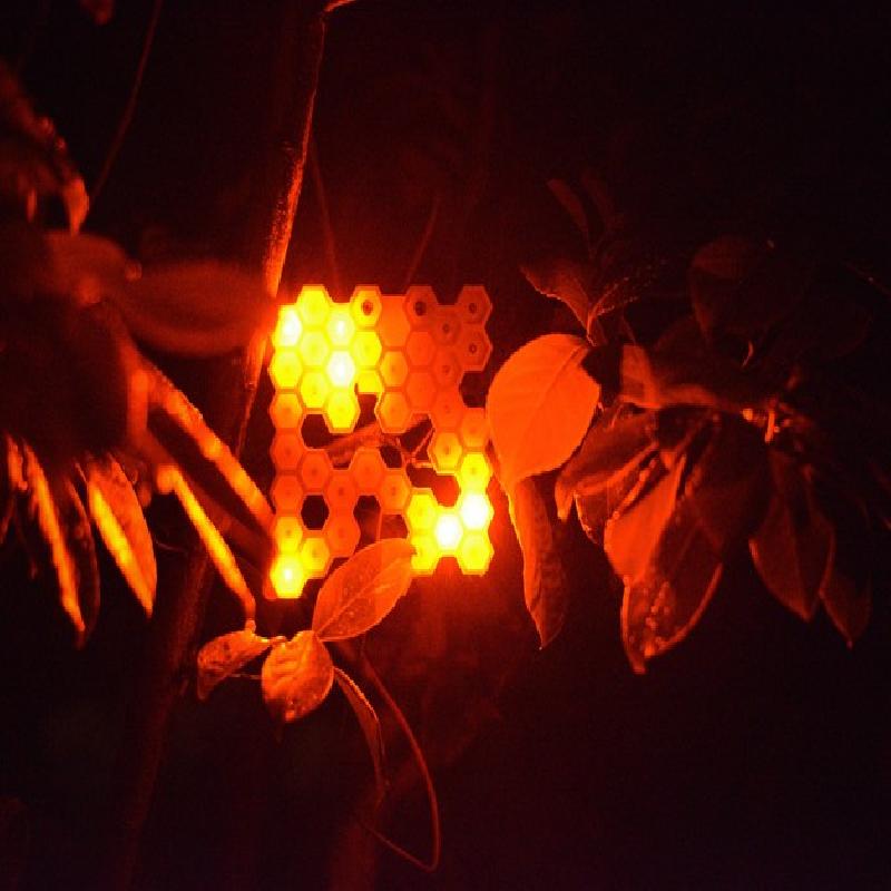
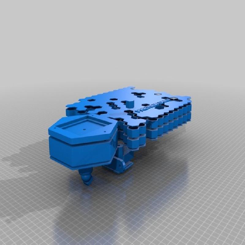
Random parametric "bee hive" LED lamp.
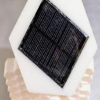
Fully customizable, optionally solar powered. Solar cell can be mounted on the back or somewhere else entirely.
I will upload some example .stl files - make your own one with OpenSCAD or Makerbot Customizer.
Can be powered by 4 - 12 V like a "normal" LED lamp or as a solar powered outdoor night lamp that recharges during the day and glows in random patterns during the night in a specified time frame.
Measured standby energy consumption is below 10 mA, operational power consumption bounces between 20 and 80 mA ( depends on the amount of LEDs glowing at the time).
May get some improvements down the line.
Video:
https://youtu.be/Jzrjw_V_L-Y
Building process:
http://imgur.com/a/qvXDF#0
Short operating gif:
http://imgur.com/9cCyTXW
Added "SolarHive_DemoAllPartsRC5.zip" which contains all the files to build the Solar Hive Lamp you see in the pictures and video. (Updated von AllpartsofDemo.zip on August 5th)
Update August 3rd:
fixed some errors in the arduino sketch. The new one is SolarHiveArduinoSketchRC5.ino and downloadable from "Thing Files"
Update August 5th:
Replaced "AllPartsofDemo.zip" with updated Files.
Added "SolarHive_DemoAllPartsRC5_4inch.zip" which contains the demo .stl files split into sub 10 cm ( 4 inch ) parts. ( and rectangular solar and battery housing )
Full Instructions as .pdf added to the Thing Files.
1 Introduction
The idea was to create a lamp dedicated to the beauty of randomness, so the shape and the glowing pattern are randomized.
All the body parts are 3D printed and the electronics should cost less than $ 25 or 20 € in total.
To create your own lamp you can use OpenSCAD or the Thingiverse Customizer to change the parameters according to your needs.
You will need basic soldering skills and an ISP or a second Arduino to upload the arduino sketch to the micro-controller board – or just do it your way and don't stick too closely to this manual.
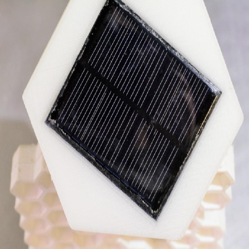
The 6V 110 mA solar cell charges 4 NiMH batteries during the day.
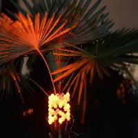
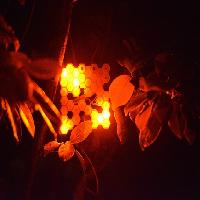
If it gets dark for a long period of time (30 minutes, you can adjust it in the Arduino sketch) an algorithm lets the LEDs glow in a randomized order.
After around 2 hours the light will switch itself off and wait for dawn to start recharging.
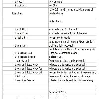
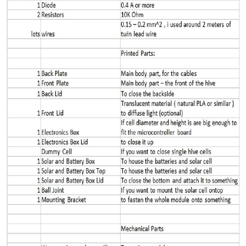
2 Parts
Under"Thing Files" is a list of all the parts i used to build my lamp. Your parts may differ, especially the amount of LEDs ( I used 38).
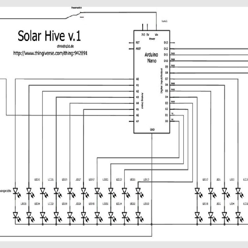
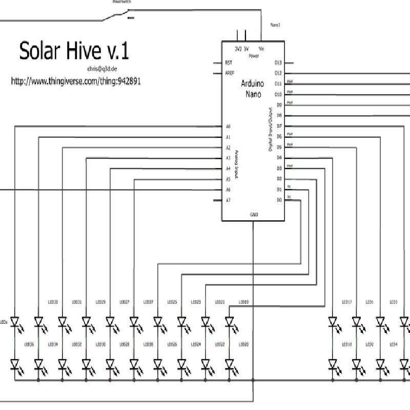
With the Atmel 328P based microc-ontroller board we can use up to 20 channels to power our LEDs with 2 LEDs each.
I used a "dswy_robot" called Arduino like board which is pretty cheap, small and uses very little energy.
The one downside is it lacks an USB port, which means you'll need another Arduino or another ISP ( In-System Programmer) to upload the sketch.
More Info about the Uploading process here: https://www.arduino.cc/en/Tutorial/ArduinoISP
While testing i measured below 10 mA standby and around 20 to 80 mA in operation.
The solar cell i used has 0,75 W, 6 V, 120 mA but anything between 5 - 7 V and 60 - 400 mA will work.
The rechargeable batteries i used are 4 NiMH AAA cells with 1.2 V each - you should only use NiMH or sealed lead-acid batteries for this kind of un-monitored circuit.
Since we've only got 4.8V max. to work during nighttime we'd need resistors for usual 3.0-3.6 V LEDs.
But if we take orange or red LEDs which run at 1.9-2.4V we can power 2 of them in series on each channel.
Usually we would have to add a small resistor in each line but since we're maxed out at 4.8 V anyway ( ideally 2 x 2.4 V, divided between our two LEDs) and our micro-controller powers the LEDs only for short time periods via PWM signal we can do without resistors.
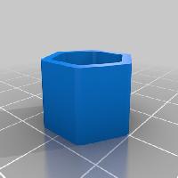
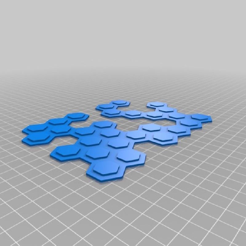
3 Customizer
Use OpenSCAD or Thingiverse MakerBot Customizer to create the 3D printed parts you'll need to build your own Hive.
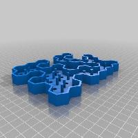
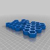
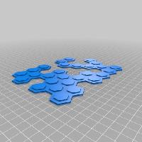
You can adjust all the parameters to your likings, in the part selection menu chose a preview setting like "Preview All Hive Parts" to get started.
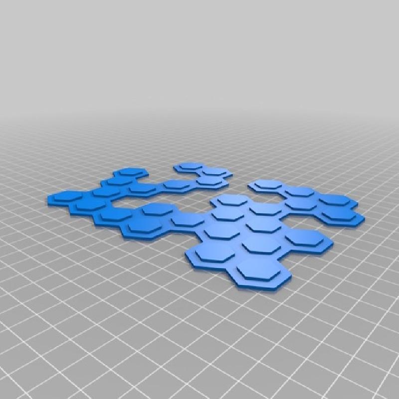
With the parameter "Seed" you can change the input for the randomizing algorithm, simply try different numbers and take a look at the preview ( F5 in OpenSCAD ). Often the random pattern is not one single connected part, if that is the case simply change the number to something different and refresh.
Or adjust the "Varamount" Variable - it determines how many of the cells are rendered. It ranges from 1=none to 10=all. Between 6 and 9 are good values.
Below 5 it will be hard to get one connected part.
"Cell Diameter" determines the diameter of each cell. This plus wall strength times number of cells in each direction gives you the overall size of the hive.
"Wall strength" changes the thickness of the walls around the cells. 1 - 3 are good values, for bigger cell diameters a higher value may look more pleasing. A higher value will also increase the sturdiness, weight and printing time of your hive.
"Led Hole Diameter" changes the hole in the middle of each cell. For 5mm LEDs i recommend 5.4, for 3mm LEDs 3.4. You may need to adjust this parameter depending on your printer & slicing software. The LEDs should tightly fit into the holes.
"Lengthx" changes the upper number of cells in x-direction,
"Lengthy" in y-direction.
"Heightcell" adjusts the height of each cell, your hive will be a little more than double that amount.
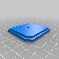
"Cell Bottom Strength" determines the thickness of the base of each part. 1 or 2 should be enough.
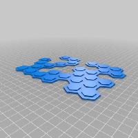
"Booleanledhole" - here you can disable the LED holes in the middle of each cell, only useful if you just want to make an hexagonal storage board or something similar.
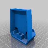
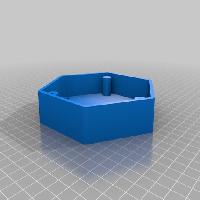
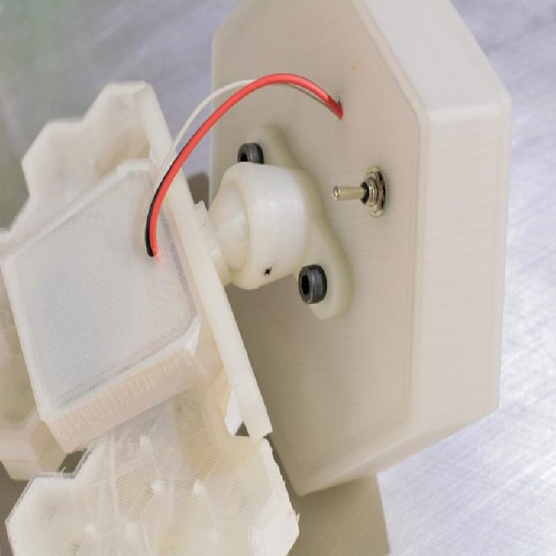
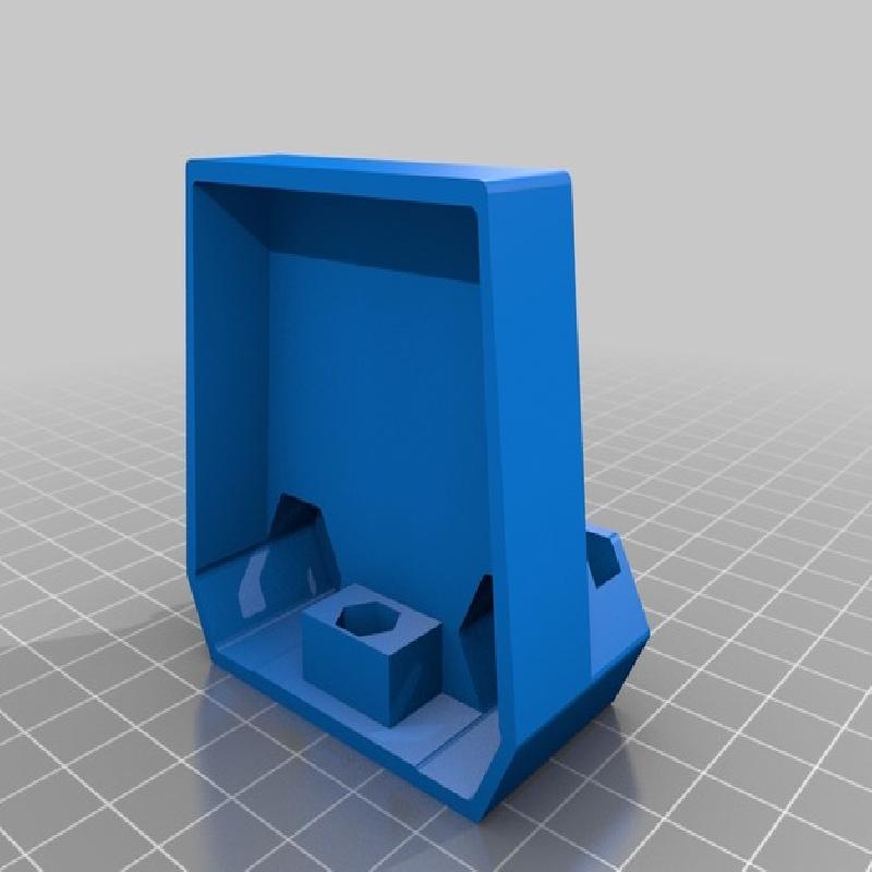
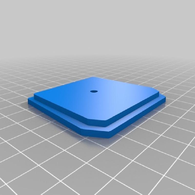
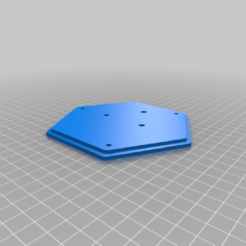
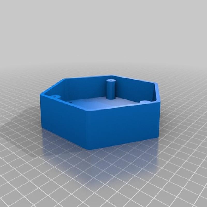
Tab "Electronics box"
The electronics box is only needed if you can't fit all the parts in the back plate. For a simple plugged 12V Lamp or a huge cell diameter you won't need this part.
"Electronics Length" determines the length of the box, for my small dswy_robot board a value of 35 gave me enough room to store extra cables, the width will be determined by the cell diameter. ( ~ 2.5 * cell diameter )
"Electronics Height" changes the height of the box, it will automatically add 10 mm to the value for cable management.
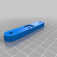
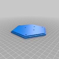
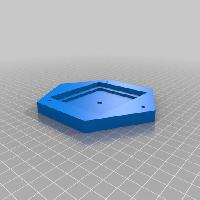
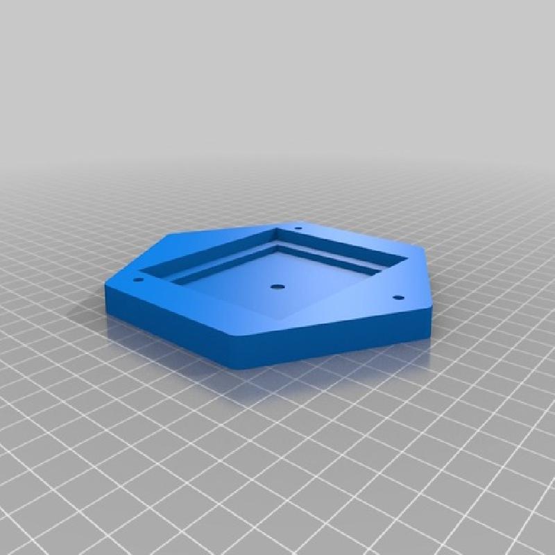
"Mphd" changes the width for the mounting plate - a simple plate that you can screw between the ball joint and the electronics box. The Value gives you the mounting hole distance.
"Ardumounthole" adds the mounting hole on top of the electronics box - useful only if you want to add the solar cell and battery box on top of your hive with the ball joint.
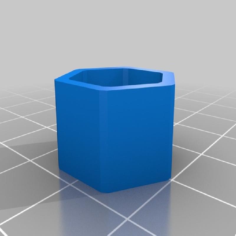
Tab "Solar cell and battery pack"
Here you can adjust the Box which will contain the battery pack and the solar cell. Should be pretty self-explanatory.
I may add options for different mounting methods and a rectangular shape for the solar and battery box down the line.
4 Assembly
Building process:
http://imgur.com/a/qvXDF#0
Assembly Instructions:
(One with pictures is downloadable from Thing Files as .pdf)
Customize your own Hive Lamp or download one of the complete examples uploaded to Thingiverse.
If you're exporting your own .stl files be sure to use the same parameters for every part so they will fit later.
Print the Parts, you won't need fancy settings but make sure the wall strength is thick enough ( 1 mm or more ).
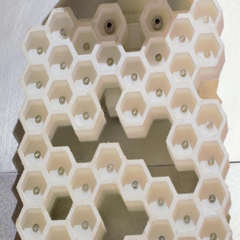
Place the front plate of the hive onto the back plate, you can glue them together if you like ( the LEDs will connect them anyway).
Front side down, start pushing the LEDs into the holes from the back. To make soldering easier align them all in the same way - long lead (anode) to the left, short lead (cathode) to the right.
You can add up to 40 LEDs to the solar powered lamp.
If you want to add the micro-controller in the printed electronics box leave 2 suitable holes empty.
Add some drops of super-glue on the edges of each led to seal them.
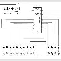
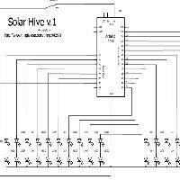
Now you need to connect the LEDs with some wires. 2 LEDs in series will be connected between a suitable pin of the Arduino and GND. (Take a look at the circuit diagram !)
The first wire should be long enough to easily reach the micro-controller board later on, so lay them from one of the empty cells that will later be used to mount the electronics box to the LED you want to connect and add 10 cm ( 4 in ).
Solder the wire to the long lead ( anode , + ) of the LED near the head of the LED and cut off the remaining long lead.
Leave the short one (cathode, -) intact. Do this for exactly half of the LEDs. Prefer LEDs near the port to the Electronics Box.
After that connect the long lead ( anodes, +) of a random remaining LED to the short lead (cathode, -) of a random LED we soldered a wire to earlier.
Make sure the wire connecting 2 LEDs is exactly as long as it needs to be in order to be laid inside the printed back plate.
Do this for the remaining LEDs until all anodes and half of the cathodes are connected and shortened.
Now use a different colored wire ( preferably black or blue) to connect all the remaining cathodes together.
Take the printed cover for the back plate and try to fit it, if there are leads in the way bend or shorten them ( if possible ) so it fits.
Use some scissors to cut out the two cells of the back plate lid where the electronics board will be mounted later and all the wires unconnected are ending now.
Test each pair of LEDs by briefly connecting them to the charged NiMH cells or another 4 - 5 V power supply.
( Arduino will work, 5V and Ground Pins) Therefore the black "all" cathode cable is connected to GND ( - ) and the anode of each LED pair is briefly ( ! ) connected to VCC ( + ) ( 4 - 5 V ).
Each LED pair should work, if one doesn't check their wiring.
If all the LEDs function properly use lots of silicone or water resistant glue to join the cover / lid and the back plate.
Now pull the wires through the feet of the electronics box.
Use short M5 bolts & nuts to join the cell structure and the electronics box or use glue or silicone.
Now to the micro-controller board. First solder the Pins the the ISP header.
Now download the Arduino sketch ( the .iso file from Thing Files).
If you don't have Arduino IDE to open the file go to https://www.arduino.cc/ and download the newest IDE.
Arduino IDE is an open source software that makes it easy to write and upload instruction sets to Atmega micro-controllers.
Adjust the parameters inside the sketch to your liking or improve and share it.
You will need the SoftPWM library, it allows up to 20 channels of PWM output.
Download and installation guide should be here:
https://code.google.com/p/rogue-code/wiki/SoftPWMLibraryDocumentation
Arduino ISP:
Now connect your standalone Arduino to your PC via USB and press "File" -> "Examples" -> "ArduinoISP".
Under "Tools" tab you can chose the Arduino board you have and the "com port" where it is connected.
E.g. Arduino Uno on COM3. Now press the Arrow to compile and upload the Arduino ISP sketch.
In the sketch itself and on https://www.arduino.cc/en/Tutorial/ArduinoISP are some Instructions how to wire your Arduino as ISP to another micro-controller board to upload sketches.
Uploading the sketch:
If everything is wired up correctly you can switch to the hive sketch and use "File" -> "Upload Using a Programmer" to upload it to the small micro-controller board that will control your hive lamp.
Make sure to select the proper Arduino board under the "Tools" tab ( Arduino mini ).
To save energy you can disconnect the power LED on the Arduino board, nobody will see it mounted inside anyway.
Use your soldering iron to heat and push the SMD resistor right below the power led out of it's connections.
Disconnect the two and now start connecting the LED pair anode wires to the Pins 0-12 and A0-A5, the cathode cable to a GND pin, add a long wire to A6 that will later on check the solar cell status and add a twin paired wire to the power connections VIN and a spare GND.
Lead the three extra wires through the hole electronics box cover.
The length of these wires depend on where you want to mount the solar cell and battery housing.
Solar cell and battery housing:
Solder a 10cm ( 4 in ) wire on the solar cells lead-outs and glue it into the cut-out of the top cover with the wire running through the hole.
Now screw or glue the top part onto the main part.
Place the battery pack inside.
Funnel the three wires from the controller board through the hole of the bottom cover.
We'll need to add two 10k Ohm resistors, a diode and the switch to complete the circuit. I soldered them onto a leftover piece of prototype board, but you can solder them in between the wires as well.
The two resistors are connected in series between the wires of the solar cell.
The wire from the A6 pin of the micro-controller is connected in between them.
The diode is connected between the ( + ) wire of the solar cell and the ( + ) wire of the battery pack. The diodes anode is to face the (+) wire of the solar cell, the diodes cathode ( marked with a small ring on the housing ) should face the ( + ) wire of the battery pack.
The diode prevents the batteries to discharge themselves over the solar cell during the night.
Now also connect the ( + ) wire of the battery pack to the toggle. Connect the VIN wire from the micro-controller board to the other pin of the toggle.
Now connect the ( - ) of the solar cell, the battery pack and the GND wire from the micro-controller board together.
If your batteries are charged you can test the circuits by covering the solar cell and switching the lamp off and on again.
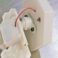
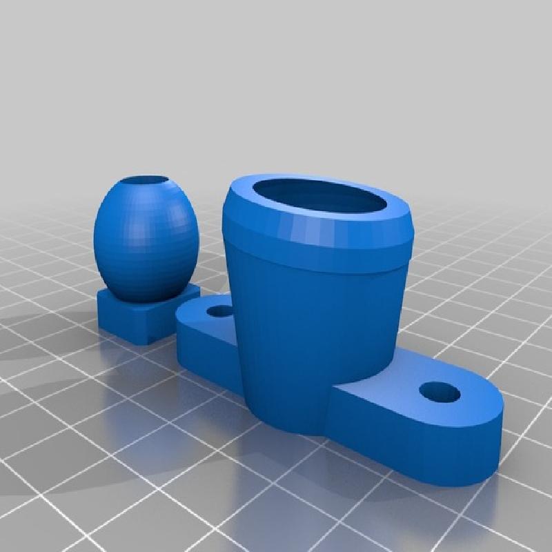
If you want to mount the solar cell and battery box on top of the lamp use a M5x25 bolt and M5 nut to join the ball of the ball joint, the mounting plate and the electronics box.
Cut a M3 thread into the hole on the side of the cup of the ball joint and add a grub screw or short M3 screw into it ( or just glue them together once aligned).
Use two M5x10 screws to mount the cup of the ball joint onto the solar cell and battery box.
Cut M3 threads into the pillars of the box.
Now screw the top, main part and bottom cover together with M3 screws.
If everything is operating satisfactorily use plenty of silicone to waterproof everything if you want to keep it outside.
Push the ball joint together until they connect, place the lamp, align the solar cell and fasten the grubs crew or glue them in place.
5 Operation
Place the Solar Panel at a place that gets lots of sunlight during the day, preferably facing south.
If you switch it off the batteries will still get charged.
If you turn it on during daytime it will continue to collect energy until the solar cell can't provide any more energy. Then a countdown starts, if it stays mostly dark during the next 25 minutes the lights will start their randomized play.
After 3 hours the light will switch itself off again and wait for daytime to return (to get charged again).
If you want to turn it on at a random time: cover the solar panel so it is dark and switch it off and on again.
If it's turned on during darkness it will skip the waiting time and start right away.
All the values are adjustable to your liking in the Arduino sketch.
If the solar cell doesn't get enough light to keep the batteries charged you can remove them and charge them with a normal NiMH capable battery recharger.