
by macakcat, published
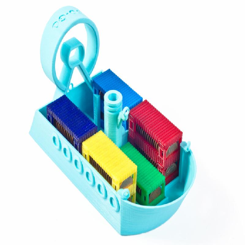
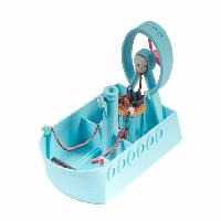
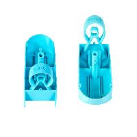
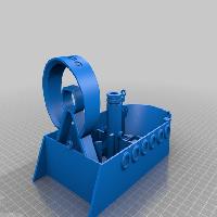
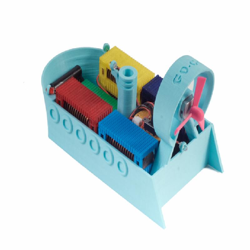
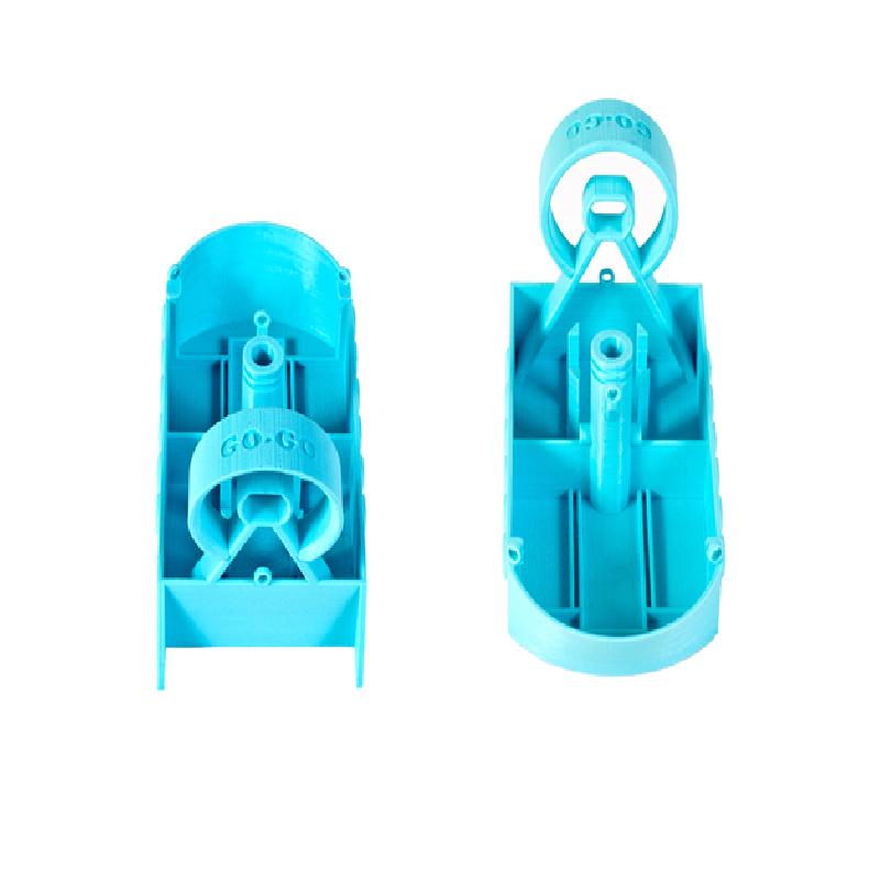
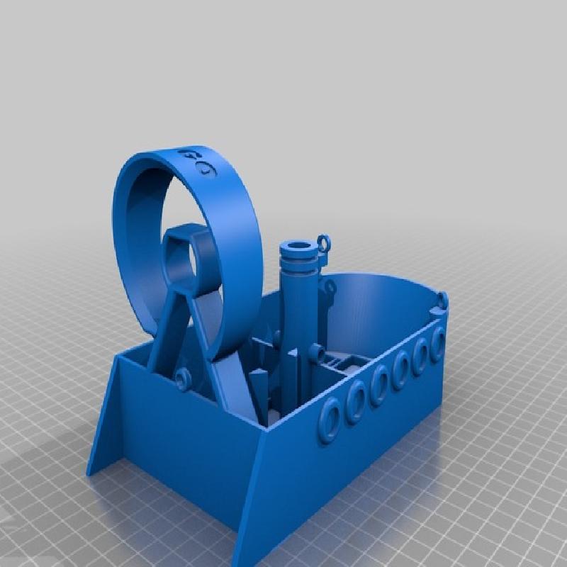
GO-GO AirBoat is a payload-sensing, motorized, propeller airboat.
When GO-GO AirBoat reaches full capacity, watch the motor rev to life, spinning the propeller, and watch GO-GO go! How many pennies can you load before GO-GO goes? Will it sink or will it float? Load your lifesavings aboard, and wave "Bon voyage!" to your GO-GO AirBoat!
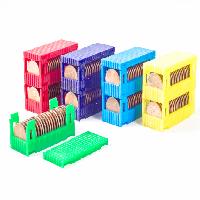
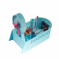
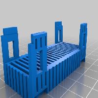
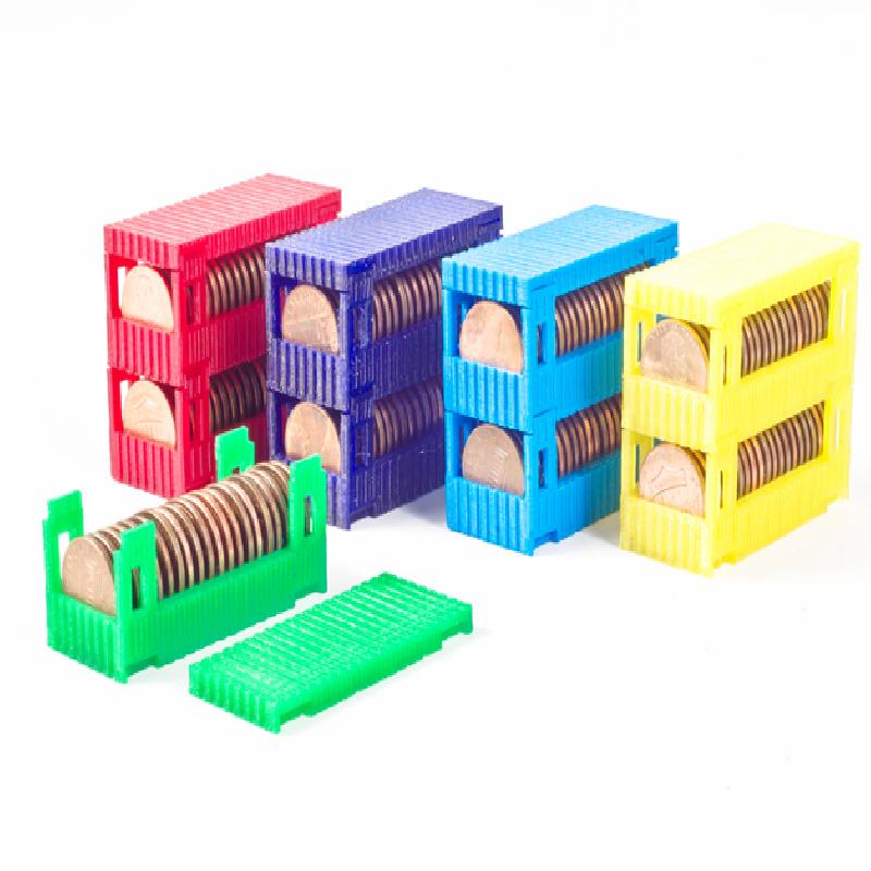
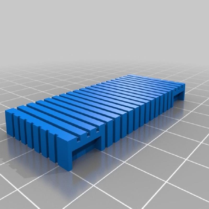
Load your cargo containers with up to 20 pennies each (US cent tested). The cargo containers are infinitely stackable! GO-GO's cargo bay area can support up to 5 columns of cargo containers. Many combinations of load and weight distribution possible. Experiment!
Provided instructions include derivation of the "Maximum Number of Pennies" equation to stay afloat with your chosen cargo configuration.
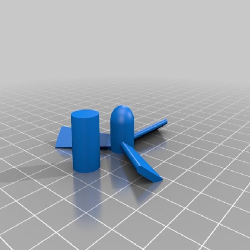
Simple to print! There are only four STL files needed to construct your GO-GO AirBoat and cargo containers so it's easy to do.
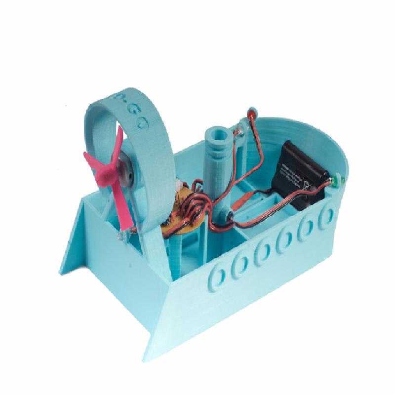
GO-GO AirBoat senses when to embark on its long haul across the sea when it is fully loaded to capacity with its valuable cargo. A floating piston inside the boat's smokestack is free to move with the water level and triggers the motor to drive when a certain depth is achieved. This sensor employs a simple infrared LED, phototransistor, and a Darlington pair transistor amplifier stage for switching of a small DC motor.
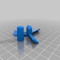
The depth-sensor trigger point can be mechanically altered using different, floating piston heights of your own creation.
Gain hands-on experience with resistors, capacitors, diodes, LED's, DC motors, bipolar junction transistors (BJT's), Darlington pair transistors, phototransistors as triggers, circuit board layout, and soldering.
The GO-GO AirBoat features a series of basic, discrete component, electronic constructions to help young engineers and future scientists better visualize electrical components, their wiring, and their roles in electronic circuits. The instructions provide step-by-step calculations and descriptions of how the individual circuits function together as a whole.
Use this model as an activity or introduction to subjects such as weight, mass, displacement, density, buoyancy, and center of gravity. Topics covered within the instructions focus on mass, density, and basic algebra. Logic and reasoning skills are exercised to translate calculated values to the real world.
Designed by David Choi
I wanted to create an educational piece that one can learn from and expand on, by developing and enhancing fundamental and motivational experiences while building, testing, and playing. Mathematics, physics, and electronics weren't the easiest things for me to learn, but I think with passion you can learn anything, and this can be rapidly fueled by successful, real-world experiments that are made fun. This introductory project is geared towards young minds, novices, students, DIYers, enthusiasts, the different, and the like, for exploration, experimentation, and positive iteration.
WHAT DOES GO-GO AIRBOAT DO?
HOW IT WORKS
MY PRINTER SETTINGS & POST-PROCESSING TECHNIQUE
PRINTING TIPS & TROUBLESHOOTING
THE PROBLEM & THE PHYSICS IN A NUTSHELL
ASSUMPTION
WHAT YOU KNOW
WHAT YOU DON'T KNOW
WHAT YOU MEASURE
MEASURING THE "VOLUME DISPLACED" (Vd)
CALCULATIONS AND OUR FINAL EQUATION
RECOMMENDED TOOLS & ITEMS
WHAT YOU NEED FOR THE CIRCUIT
WHERE TO FIND ELECTRONIC PARTS
THE CIRCUIT EXPLAINED
HELPFUL CIRCUIT & BOAT ASSEMBLY TIPS, TRICKS, & TROUBLESHOOTING
YOUR FIRST VOYAGE
FURTHER EXPLORATION, COLLABORATIVE EXERCISES, & EXPERIMENT IDEAS
YOUR NEWFOUND SKILLS
DISCLAIMER
The GO-GO AirBoat, as provided, is a payload-sensing, motorized, propeller airboat. It has a large, payload volume capable of housing cargo containers full of pennies or... WHATEVER FLOATS YOUR BOAT.
GO-GO features an easily accessible, hackable, optical sensor and mechanical component to sense how close it is to sinking from payload overload.
GO-GO comes with cargo containers which hold 20 pennies each and stack together to form any configuration you'd like.
Use the included equations derived in the instructions to calculate the number of pennies and cargo containers your GO-GO can hold without sinking.
What's more interesting is what you can make GO-GO do for you. Think of GO-GO as a mobile, floating platform for your imagination.
Load your cargo containers with pennies in any order or amount you want and cross your fingers...
Or play it safe and use the equations derived in these instructions to calculate the maximum number of pennies your GO-GO AirBoat will carry with your cargo configuration to stay afloat, then test it out in the real world.
Cargo containers stack and snap together to increase payload capacity. Up to 20 pennies per cargo container.
GO-GO AirBoat will sit idle as you load your cargo containers.
When GO-GO reaches capacity, the propeller will spin and send your precious payload scooting across the pool!
GO-GO AirBoat has a depth sensor designed into its smokestack. The depth sensor employs an infrared (IR) diode transmitter-phototransistor pair, and a floating piston to trigger the IR gate when it blocks the beam.
The piston floats freely with the water level within the smokestack which is open to water flow underneath the hull. A catch in the hull at the bottom prevents the piston from falling through.
Pistons of different heights may be experimented with to alter trigger levels. The stock piston contained within the propeller print file ("GoGoAirBoatParts.stl") is 1.0cm in diameter and 1.5cm tall.
MakerBot Replicator 5th Gen
1.75mm PLA
No Rafts
No Supports
Temp at 214°C*
0.20mm Resolution
Infill at 10%
3 Shells (The model was designed with 3 shells in mind)
First Layer at 30mm/s (This helps a lot to get a watertight seal!)
Insets at 80mm/s
Outlines at 18mm/s*
Everything else, Standard Settings
No Post-processing Needed
No Glue nor Resin Needed
*My current extruder tends to ooze on outlines so I lowered the temperature and decreased the speed around outlines.
Level your build plate first!!! Make sure your build plate is as level as possible. After leveling, I suggest printing the cargo containers first to get a feel for how level the build plate is before printing the boat. Each layer should be printed level, tight-knit, and solid. Be sure to have your Z-offset fine-tuned as well. If the prints are coming out poorly and you insist your build plate is level, then you may want to clean or replace your extruder nozzle. In my experience, persistent extruder jamming is a sign of a worn out extruder or improper Z-offset. If it lays down filament that doesn't stick or wiggled back and forth like a snake on the build plate, it's too high. Alternatively, if you hear repetitive clicking sounds from your extruder, it's too close, or your extruder is clogged or wearing out. During proper extrusion of the print itself, you will not hear any clicks and the filament will lay down firm and thin in height.
No need to rescale provided STL files. I drew them to scale.
Carefully observe the first few layers of your print. You'll be able to recognize when a print is going to be successful or not with a keen eye and a little, systematic persistence and experience. Your first layers should adhere well to the build plate and the lines should interlock solidly.
If your prints aren't working with your favorite settings, please give my settings a try. I used PLA.
"How do I remove this huge model from the table (on painter's tape)?" I've always used a guitar pick, starting at the corners and gently working around the edges (specifically, yellow, Dunlop Tortex guitar picks since I have a lot of those--0.73mm thickness). That's my two cents. I've never researched what other people do but this works for me. If you've got a great method, share it!
"My boat is far from watertight, dude!" You need to make sure your build plate is level and your Z-offset is optimal. Experiment with slower extrusion speeds and different temperatures by a couple degrees. After careful leveling I did have a successful, watertight print. If all else fails, resin or superglue-seal that hull, or simply start with a fresh nozzle to finally rid yourself of any treacherous, printing gremlins.
We want to calculate the maximum number of pennies we can load onto the GO-GO AirBoat before it begins to sink. Hopefully your GO-GO AirBoat will shove off before it reaches this maximum penny value. Since we're loading the pennies into cargo containers, it'd be nice to predict if our next container will lead to a sunken disaster or not.
Boats float due to their buoyancy in water. Buoyancy is a function of the volume of the fluid displaced and the density of the fluid displaced, along with the local acceleration due to gravity. The less dense object will be more buoyant (float), and the denser object will be less buoyant (sink). In our case, so long as our boat is less dense than the water it displaces, it will stay afloat!
So let's figure out the maximum number of pennies we can load using any configuration of cargo containers...
All pennies have an average mass of 2.5g.
Density = (Mass) / (Volume)
"Density of Water" = Dwater ≈ 1g/cm^3
"Mass of a Penny" = Mp = 2.5g
Note that at sea-level on Earth, "weight" [kg] and mass [kg] are interchangeable...
→ "Weight of a Penny" [kg] = Wp [kg] ≈ Mp [kg]
This is important since we'll be doing several weight measurements later on (most likely you're using a spring scale or digital scale) but we'll be needing their masses instead for our equations and calculations.
We'll use this mass-to-weight relationship to help simplify calculations.
You may already do this conversion automatically in your head and never think twice about it, but it's a good idea to understand why we can do this on Earth. This explanation also helps us see why notation and the true meaning behind the notation is so important in physics problems.
Balances measure mass directly by canceling out the local gravitational force on either side of the fulcrum, but you need a known, calibrated mass to measure against. Your household spring scales and digital scales, on the other hand, directly measure forces, namely weight. You probably have a spring scale or digital scale and not a balance, so we're going to say these measurements are of mass for simplicity's sake. This is a valid approximation for our sea-bound GO-GO.
Let, x = "Maximum Number of Pennies"
We want to solve for the maximum number of pennies the GO-GO AirBoat can carry. So this means we need to solve for the variable x, where the density of the volume displaced by the ship is less than the density of water--that's almost the boundary where our ship floats or sinks.
We need to solve for x when:
Dgg < Dwater, where Dgg is the "Density of the Loaded GO-GO."
To do that, we'll first need to find out what the "Total Mass of Loaded GO-GO" (Mtotal) is, since it can be seen that Dgg = (Mtotal) / (Vd) from the Density equation, where Vd is the "Volume Displaced."
Let, Vd = "Volume Displaced" = ( ? cm^3); Where, 1mL = 1cm^3.
Let, Mgg = "Mass of GO-GO with Electronics and Battery, Unloaded" = ( ? g)
Let, Mcc = "Mass of a Cargo Container, Unloaded" = ( ? g)
Let, Mcl = "Mass of a Cargo Lid" = ( ? g)
A method to measure the full displacement of the ship at capacity would be to put a large bowl inside a larger empty bowl, fill the inner bowl to the brim with water, and dunk the boat to the desired depth (the maximum depth you think the GO-GO can handle, or when the depth sensor is triggered--these are designed to be similar in value). Any displaced water caught in the outer bowl can now be measured off with a measuring cup or even better, weighed with a scale. For some reason I don't actually have any bowls, measuring cups, a scale, or any basic kitchen utensils in my apartment so I never tried this myself.
An alternative, less useful method is to just measure the volume of the inside of the cargo area of the boat hull alone. This will clearly give you an incorrect, undesirable, or otherwise completely wrong answer but this can be done with a small measuring cup swiftly. Your calculation will be off by a decent number of pennies, possibly resulting in a sunken ship. Just keep this in mind.
Let, a = "Number of Cargo Containers"
Let, b = "Number of Cargo Lids"
"Total Mass of Loaded GO-GO" = Mtotal = (Mgg) + a • (Mcc) + b • (Mcl) + x • (Mp)
Recall, from the equation for Density, we have...
"Density of Loaded GO-GO" = Dgg = (Mtotal) / (Vd)
→ Dgg = [ (Mgg) + a • (Mcc) + b • (Mcl) + x • (Mp) ] / (Vd)
So how do we relate to the "Density of Loaded GO-GO" (Dgg) then?
Remember our stipulation for solving for x? (Hint: "We need to solve for the variable x, where the density of the volume displaced by the ship is less than the density of water--that's almost the boundary where our ship floats or sinks.")
I know what you're thinking. You're right.
We need to find Dgg < Dwater, and we know Dwater ≈ 1g/cm^3.
→ Dgg < Dwater
→ [ (Mgg) + a • (Mcc) + b • (Mcl) + x • (Mp) ] / (Vd) < (Dwater)
→ x < [ (Dwater) • (Vd) - [ (Mgg) + a • (Mcc) + b • (Mcl) ] ] / (Mp)
→ "Maximum Number of Pennies" < [ (1g/cm^3) • (Vd) - [ (Mgg) + a • (Mcc) + b • (Mcl) ] ] / (2.5g)
∴ → If the number of coins that you load onto GO-GO AirBoat is less than the right-hand side of the above equation then your GO-GO will stay afloat in water!... Right?
Almost: The answer must be an integer value since we are talking about whole pennies, not partial pennies.
(Why minus one penny? Since an integer value is an indication that the values are exactly equal even with rounding of the "Maximum Number of Pennies," we need to subtract one whole penny in order to satisfy the inequality.)
Multimeter (Ammeter, Voltmeter, Ohmmeter, Diode Checker, Continuity Checker)
Soldering Iron and Stand/Station
Helping Hand Alligator Clamps
Solder
Damp Sponge
Solder-Sucker or Desoldering Braid
Wire Strippers
Small, Bird Beak, Side Cutters
Small, Heat-shrink Tubing
Breadboard
Breadboard Jumper Wires
Scale [grams]
Measuring Cup (optional)
1/8" Drill Bit (optional)
(1) - 3.6V, 800mAh, NiMH battery pack (or simliar)
(1) - Male/Female JST connector pair for the battery (or similar)
(1) - 130-size, 4.5V to 6V, DC motor (This is a small, hobby motor)
(1) - 1N914 small signal, switching diode (This little guy will survive but equivalent or better, such as 1N4001 or something)
(1) - 1,000uF, 10V electrolytic capacitor
(1) - SPST Switch (rated for at least 1 amp)
(2) - 2N2222, NPN Transistors (or equivalent)
(1) - Infrared (IR) Emitter Diode (5mm)
(1) - NPN 5V Phototransistor (5mm)
(2) - 1kΩ, 1/4W Resistors
(1) - 100Ω, 1/4W Resistor
(2) - 220Ω, 1/4W, Resistors
(4) - 5mm LED's (I used 2 white, 1 red, and 1 green to mimic ship lights.)
(1) - Round PCB (45mm diameter purchased at RadioShack. If you don't have that, don't fret, a rectangular board will work better. Try 50mm x 40mm or 40mm x 40mm.)
Lengths of Wire, ~22AWG (stranded preferable)
For this project I went to RadioShack.
RadioShack (Essentially all parts can be found at your local store if you like walking)
The JST connector I had on hand from Adafruit. The motor I had around from somewhere but Adafruit carries a very similar one.
You can also use these awesome sites below:
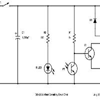
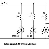
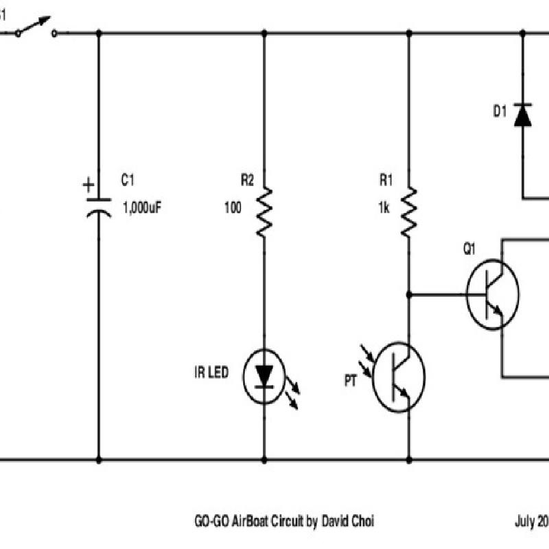
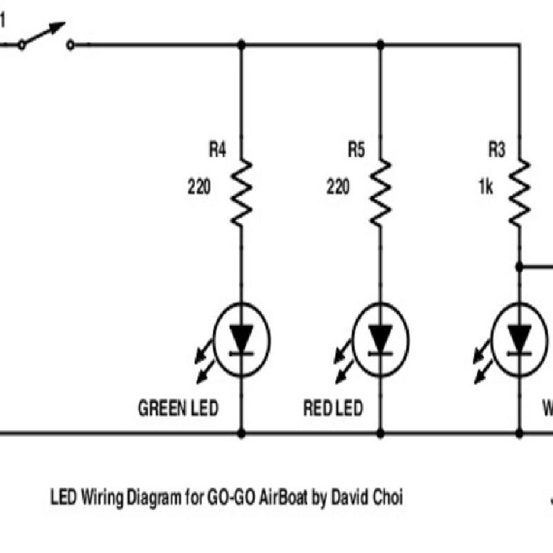
The main components of the electric circuit are an infrared (IR) emitter-phototransistor pair; the NPN, Darlington transistor pair; and the DC motor. Those are the important parts. The circuit can be broken down into 5 smaller sections to cover every part's function. I've provided the circuit diagram as two separate diagrams included in the image files for GO-GO AirBoat. The first diagram is of the main driving circuit and sensor. The second diagram is for the decorative LED's.
R1 = 1kΩ, 1/4W Resistor
R2 = 100Ω, 1/4W Resistor
R3 = 1kΩ, 1/4W Resistor
R4, R5 = 220Ω, 1/4W Resistor
IR LED = 1.2Vfwd, 100mA max
C = 1,000uF, 10V Electrolytic Capacitor
D = 1N914 Diode
M = 4.5V - 6.5V DC 130-Motor, 250mA
PT = Phototransistor, 50mA max, 150mW max
Q1, Q2: 2N2222; 600mA continuous, 625mW max
The Power Supply and Main Power Switch
This is the simplest section to explain. This circuit is extremely basic and utilizes no proper voltage regulation. That's why battery voltage selection is important. The power supply is a constant voltage battery of 3.6V with a power switch connected in series. The polarized, electrolytic capacitor in parallel with the whole circuit is there to help smooth current draw from the battery and prevent supply voltage dips across the rest of the supply when the motor turns on. It's main purpose in this circuit is to prevent the LED's from flickering too much when the motor turns on. A dedicated voltage-regulating chip would help cure this with the help of a slightly higher supply voltage requirement.
The DC Motor and Flyback Diode
The circuit is designed around the 4.5V motor and its current draw. We'll need to be sure the transistor Q2 can handle the power dissipation, which we'll calculate later on. See the "Bipolar Junction Transistors (BJT's) and the Darlington Pair formed by Q1 and Q2" section for calculations for the motor and transistors.
The flyback diode protects the supply and transistors and decreases back EMF generation by the motor. It's common practice to put one in reverse, in parallel with the motor terminals for a single-direction DC motor. If you happen to try to run the motor in reverse, you'll blow the diode from excessive current.
The LED's and IR Transmitter Diode
The red and green LED's have 220Ω resistors in series with them, the IR transmitter diode has a 100Ω resistor, and the white LED's share a 1kΩ resistor because they're very bright. The forward voltage drops of LED's are different based upon different LED output powers and their respective colors, which makes 220Ω a safe working point. However, they may appear a bit dimmer than you'd like, but you can adjust for your LED's accordingly by following the instructions given in a moment. The IR transmitter diode works just like any other LED. If you would like to calculate resistor values for your own LED's, follow this formula:
First measure the forward voltage drop of your LED (Vfwd). Some LEDs provide this information on their packaging or datasheet.
Vfwd = "Your LED" [V] (It may be 1.2V to 1.7V for example. Use your diode checker or refer to a datasheet)
Vs = "Your Supply Voltage" [V] (This is 3.6V in our case)
I = "Your LED current" [A] (Typically 10mA to 25mA for your basic LED depending on desired brightness)
Following from Kirchhoff's Rule for our series resistor and LED circuit, we know...
→ Vs = (Vfwd) + (Vresistor)
→ Vresistor = (Vs) - (Vfwd)
From Ohm's Law, we have...
V = I • R
→ R = V / I
→ R = (Vresistor) / I
∴ → R = (Vs - Vfwd) / I
Example:
R = (3.6V - 1.2V) / (0.025A) = 96Ω
So, 100Ω will work just fine for our IR transmitter diode--it's the closest, common resistor value.
Note: Since the white LED's are so bright, I wired the two, white LED's in parallel and then in series with a single, current limiting resistor of 1kΩ. This effectively halves the current provided to each LED individually, resulting in a dimmer light that better matches the outputs of the not-so-great red and green LED's I used. This saves us from needing another resistor. See the schematic for clarification.
Extra Exercise for Beginners:
Use an ohmmeter to measure the resistance between the wiper (generally, center terminal) and other terminal of a common three-terminal potentiometer. Compare these values to the direction the knob is turning and to the schematic diagram of the potentiometer. Does the diagram make sense now? How do you wire it to reverse the direction of the resistance values?
You can breadboard your LED circuit and try adding a low value potentiometer (maybe 1kΩ) in series with the resistor and LED. By turning the knob, you can manually adjust the brightness of the LED. What you're doing is limiting the current flow through the LED when you increase the potentiometer's resistance. Don't forget the resistor in series with the LED or you might destroy it.
Bipolar Junction Transistors (BJT's) and the Darlington Pair formed by Q1 and Q2
Our goal is to calculate the necessary base current (Ibase) to be supplied to our motor with a 2N2222 (in our case, in a Darlington pair configuration).
Relevant 2N2222 specifications:
Q, max power dissipation = 625mW
Q, continuous current = 600mA
Q, β = 10
Q, Vce ≈ 0.1V @ (Ic / Ib) = 10
Our motor will draw around 150mA so one 2N2222 will be enough.
We have a second transistor, Q2 wired to transistor Q1 in a fashion called a Darlington Pair. A Darlington pair acts as a gain multiplier. Essentially, you can multiply the two gain factors (β) of Q1 and Q2 together to create a very sensitive amplifier stage we'll call Qd (which consists of Q1 & Q2).
So our new Darlington gain (β, Qd) is...
(β, Qd) ≈ (β1 • β2)
→ (β, Qd) ≈ 10 • 10
→ (β, Qd) ≈ 100
Darlington pairs, because of how they are constructed, have a different (Vce) than a single transistor.
For Darlington Pairs...
(Vce, Qd) = (Vce, Q2) + (Vbe); where (Vbe) = 0.6V (Minimum for saturation)
→ (Vce, Qd) = 0.1V + 0.6V
→ (Vce, Qd) = 0.7V
Updating our specifications for Qd as a whole, we have...
Our new Darlington pair 2N2222 specifications Qd:
Qd, max power dissipation = 625mW
Qd, continuous current = 600mA
Qd, β = 100
Qd, Vce = 0.7V
Using the power formula we can calculate the power dissipation of transistor Q2 when drawing 150mA to check if it is in range...
Ice = 0.150A
P = I • V
→ Pdissipated (of Q2) = (Ice) • (Vce, Qd)
→ Pdissipated (of Q2) = 0.150A • 0.7V
→ Pdissipated (of Q2) = 0.105W = 105mW
→ [ Pdissipated (of Q2) = 105mW ] < [ Q, max power dissipation = 625mW ]
Now that we checked our transistor won't overheat, we can finally calculate the amount of current that needs to be supplied to the base (Ibase) of Q1 in order to drive our motor with 150mA. (We don't have to evaluate the power dissipated in Q1 because it is easy to see that this is a very small amount).
Using the following formula, where (β, Qd) = 100...
Ibase = (Ice) / (β, Qd)
→ Ibase = 0.150A / 100
∴ → Ibase = 1.5mA
This means the resistor R1 must pass at least 1.5mA in order to fully turn on our Darlington pair. Also, our phototransistor must be able to sink at least this much current in order to fully turn the transistors off.
Before moving on, we must calculate the voltage across the base and emitter for a Darlington pair (Vbe, Qd).
(Vbe, Qd) = (Vbe, Q1) + (Vbe, Q2)
Where,
(Vbe, Q1) = 0.8V (at 150mA)
(Vbe, Q2) = 0.7V (at 15mA)
→ (Vbe, Qd) = 0.8V + 0.7V
∴ → (Vbe, Qd) = 1.5V
We need to know (Vbe, Qd) because this is the voltage threshold needed to turn the transistors Qd fully on.
The Phototransistor Trigger
Phototransistor specifications:
I = 50mA max
P = 150mW max
What we want is for Qd to turn on when the IR beam is blocked; that is, when the phototransistor stops conducting. Therefore, the phototransistor is wired in series below the 1kΩ resistor. The node between the phototransistor and 1kΩ resistor where the base of Qd connects is our node of interest (Q1's base).
The 1kΩ resistor (R1) is our base resistor for Qd. We need the base resistor to pass at least 1.5mA when the phototransistor is in the on-state, and pass at least 1.5mA to the base of Qd when the phototransistor is in the off-state. In other words, at least 1.5mA must be flowing through the R1 at all times. This current is small compared to the 50mA max throughput for our chosen phototransistor, so we'll have no problem switching the current to turn Qd on and off (even if we can't sink a full 50mA through the phototransistor.)
We need R1 to supply at least 1.5V across the base and emitter (Vbe, Qd) to put Qd into a conductive on-state. Additionally, so long as the voltage across the conducting phototransistor (Vpt, ON) is less than the voltage across the base and emitter (Vbe, Qd), we can be sure the transistor Qd will remain in an off-state. This is due to the fact that the phototransistor is in parallel with the base and emitter of Qd.
→ If [ (Vpt, ON) < (Vbe, Qd) ], then "Qd is OFF"
∴ → If [ (Vpt, ON) < (1.5V) ], then "Qd is OFF"
Solving for the phototransistor (PT) in the on-state (where Qd is off)...
We know:
Vcc = 3.6V
(Vpt, ON) < 1.5V; (This is our Qd off-state condition)
We need to find a (Vpt, ON) < 1.5V where our phototransistor remains conducting.
We're in luck because I was planning ahead:
Let, (Vpt, ON) = 0.6V
(I measured this for my IR LED in series with 100Ω (R2) and distanced about 1cm from the phototransistor.)
Let's check our work:
When the phototransistor is not conducting (IR beam blocked), current to the base of Qd is 1.5mA...
Let, Ibase = 1.5mA
Vr = (Vcc) - (Vbe, Qd)
Vr = I • R
→ R = (Vr) / (Ibase)
→ R = [ (Vcc) - (Vbe, Qd) ] / (Ibase)
→ R = (3.6V - 1.5V) / 0.0015A
∴ → R = 1.4kΩ
We don't want to use 1.5kΩ because it will limit the amount of current we get, so 1.2kΩ will work. I used 1kΩ in the final circuit because I have a lot of them and that works too.
When the phototransistor is conducting (IR beam not blocked), current through the phototransistor (Ipt) is...
Vr = (Vcc) - (Vpt)
Vr = I • R
→ Ipt = Vr / R
→ Ipt = [ (Vcc) - (Vpt) ] / R
→ Ipt = [ 3.6V - 0.6V ] / 1kΩ
∴ → Ipt = 3mA
∴ → Our 1kΩ resistor should be sufficient to turn Qd off when the phototransistor is conducting (IR beam unblocked) since [ (Ipt = 3mA) > (Ibase = 1.5mA) ].
So what all this means is, our phototransistor when blocked by the piston, will stop sinking 3mA to ground with 0.6V across it, allowing 1.5mA to pass into the base of the Darlington pair (base of Q1) with 1.5V across the base and emitter. This means our transistors are turned on and delivering power to the motor.
If you add a JST connector or any connector to the battery pack, DO NOT CUT ACROSS BOTH RED AND BLACK WIRES AT THE SAME TIME. It's a beginner's mistake to forget, and you'll cause a short circuit because the battery is live! So cut one wire at a time!
I highly recommend breadboarding the circuit first to test everything out. You may want to adjust resistor values if your LED's are too bright or too dim. My two white LED's were too bright so I put them in parallel under a single current limiting resistor of 1kΩ. This saved me from having to add another resistor to the circuit.
Think ahead and give yourself enough wire length. You want to route the wires around the cargo containers. Don't be afraid to show off your wires! Be proud of your creation.
But, use the shortest wire lengths you can. Keep in mind that excessive wire length is generally bad practice for a variety of reasons, so trim them down to the right size once you get everything fitted. Measure twice! Cut once! Make sure not to take this rule too far and make your wires too short, too. Everything in balance.
"Which terminal is positive on the motor?" The positive terminal will either have a red dot next to it or a circular indentation. You know you got it right when the motor rotates counter-clockwise with the shaft facing you. Touching leads from the 3.6V battery directly to the 4.5V motor to quickly test it will not harm this motor. Just be ready because the motor body may torque over (twist) as soon as it turns on.
"My 130-size motor doesn't fit!" Don't force it too hard! I designed it with a tight fit so no glue would be required. If there is droop from the top of the motor mount, it might not fit correctly. Don't worry--to fix this, run the motor mount section under warm/hot, tap water from the sink (not boiling). Let it heat up in 20-30 second intervals and check fitment with the motor. It should fit soon enough!
"My propeller doesn't fit!" This part is meant to be press fit. If the propeller hole isn't all the way cylindrical, it might be hard to fit on the motor. In your hands, use a 1/8" drill bit and gently twist out any extra material near the opening of the hole. This is where plastic tends to overhang. Do a little at a time and check fitment frequently. It shouldn't take much work at all.
Use a calm, smooth, freshwater source such as a pool or bathtub.
At all costs please avoid saltwater, mercury, lava, or polluted rivers.
Think ahead. Plan out how many coins to load and where.
Don't rock the boat, baby! Don't tip the boat over.
Try tying a string or some floss to the boat if you want to retrieve it easily or just go for a swim.
If your GO-GO takes on water and the motor won't stop running, blow some air down the smokestack to clear it of water droplets. Excessive water will trigger the sensor.
MECHANICAL ENGINEERS & DESIGNERS
Experiment with different piston dimensions and constructions. What aspects of the triggering change with pistons of differing sizes? What size seems to work best? What happens if you alter the weight distribution of the piston?
The GO-GO AirBoat could benefit greatly from a slightly modified design. It'd be nice if it steered and there's lots of ways to do that. Implement your favorite idea utilizing 9g micro servos.
What if you could control the motor with a servo through the smokestack? How could that be designed?
Can you design a waterproof enclosure for our electronics? Allow space for the inclusion of a microcontroller and servo driver. See if you can incorporate NinjaFlex in your design as a gasket if needed.
Is there a way to make GO-GO unsinkable? A mini waterpump? A deployable airbag? Incorporate your idea into the hull of your own design. Don't forget room for the payload!
PHYSICISTS & MATHEMATICIANS
Write a general solution for GO-GO AirBoat buoyancy, while including the payload parameter variables defined earlier.
Write an equation describing the y-position of the piston floating in water relative to base of the GO-GO with the height dimension of the cylindrical piston as a parameter. Then construct a graph depicting the water levels that trigger the motor versus the piston size (height) used.
If a floating object is depressed into a liquid and released, it will tend to oscillate due to a restoring force. Write an equation that describes the periodic motion of the GO-GO AirBoat in a liquid. Assume the sides of the boat are vertical and the bottom is flat.
COMPUTER SCIENTISTS
Using the "Real-Life Penny Maximum" equations, write a code that tells us if our boat is at the brink of sinking based on selectable payload parameters (number of pennies, cargo containers, cargo lids).
Write a Processing sketch that visualizes the loading of cargo containers on the boat. Can you incorporate a code that outputs the center of gravity of the payload relative to the ship? Can you expand this with the cargo containers and pennies and create a cool interface for all of it?
ELECTRICAL ENGINEERS
Can you figure out a way to reduce the component count? What parts should be replaced?
Can you figure out a way to improve the circuit? What parts would you change or add?
Can you make it solar-powered?
In your style, how would you incorporate a microcontroller into the GO-GO AirBoat? Can you add a servo-controlled rudder with voice command? What about a smartphone app that controls the boat with BlueTooth Low Energy?
Invent a brilliant way to make GO-GO AirBoat return home from its voyage.
I hope this walkthrough was complete enough for you to have built an understanding of the inner workings of your GO-GO AirBoat. In this project you strengthened your expertise in:
Desktop 3D Printing and Troubleshooting
Algebra
Equation Formulation
Logic and Reasoning
Solving Multi-Part Equations
Thought Processes in Physics (Math for the Real World)
Soldering
Circuit Construction
Working with Resistors and LEDs
Using Bipolar Junction Transistors as Switches
Phototransistors as Sensors
Driving DC Loads (Motors)
Integrate what you've learned into your next 3D-printed project or next experiment and share your results!
If I made a mistake anywhere that led you down a dark, dark path... either up in smoke or under the waves, let me know where and I'll fix it.