
Aerospace technology advanced very quickly in the years between the First and Second World Wars. Over roughly twenty years, the state of the art evolved from fabric-covered and wire-braced open-cockpit biplanes, to sleek, metal-skinned monoplanes with retractable landing gear and enclosed cockpits. Generations of aircraft passed quickly, and many airframes were obsolete after only a few years in service.
The American-designed Curtiss P-1, which entered service in 1924, shows an early stage in that evolution. Its construction and overall layout, with the cockpit set far back behind an inline engine and fuel tank, followed the German Fokker D VII, which had arguably been the best fighter of the late war. After the war, many D VIIs had been seized by the Allies and studied.
The Curtiss P-1 was a simple machine by later standards—you can see its few indicators, controls, and its very rudimentary gunsight in this cockpit panorama from the Naval Aviation Museum. (This is the nearly identical naval F6C-1).
On the other hand, certain aspects of the P-1 reflect emerging post-war advances. Its water cooled inline engine, the 443 hp (330 kW) Curtiss D-12, was substantially more powerful than the last generation of First World War inline engines such as the Hispano-Suiza 8 or the BMW IIIa, which were around 200-230hp (~150-170kw). The D-12 was also the first aircraft engine to incorporate a cast aluminum engine block, giving it a very high power-to-weight ratio.
This powerful engine made the P-1 very fast for its time. The D-12 had powered the first aircraft past 200mph, and pushed the P-1’s racing precursor, the R-6 to average speeds above 200mph. The P-1’s various derivatives won many air races and set a number of speed records.
This P-1's sleek Art Deco lines reflect its racing heritage. Like a number of WW1-era fighters, the P-1 was equipped with two machine guns in front of the cockpit. Unlike its precursors, P-1’s guns were hidden under a streamlined fairing. Likewise, most of the inline-powered fighters of late WW1 (D VII, SPAD series, S.E.5) had a snub-nosed look because the radiators were located in front of the engine. The P-1 placed the radiator in a streamlined fairing under the fuselage, an arrangement that later became standard.
The Base of the Tree
An interesting aspect of the P-1 is how widely adapted this basic airframe was; The family of aircraft that emerged from it is sometimes referred to as the “Curtiss Hawks”. You can imagine the P-1 at the base of a branching tree. Of course, all aircraft are part of an evolution from one thing to the next, but the same fundamental design is visible throughout the Hawk line. I can’t think of another airframe that has gone through so many variations.
In army service it underwent a series of incremental improvements, ultimately leading to the P-6E
, delivered between 1932 and 1934, which featured a more steamlined front section, a three-bladed propeller, wheel spats, and a next-generation V-1570C engine rated at 700hp.
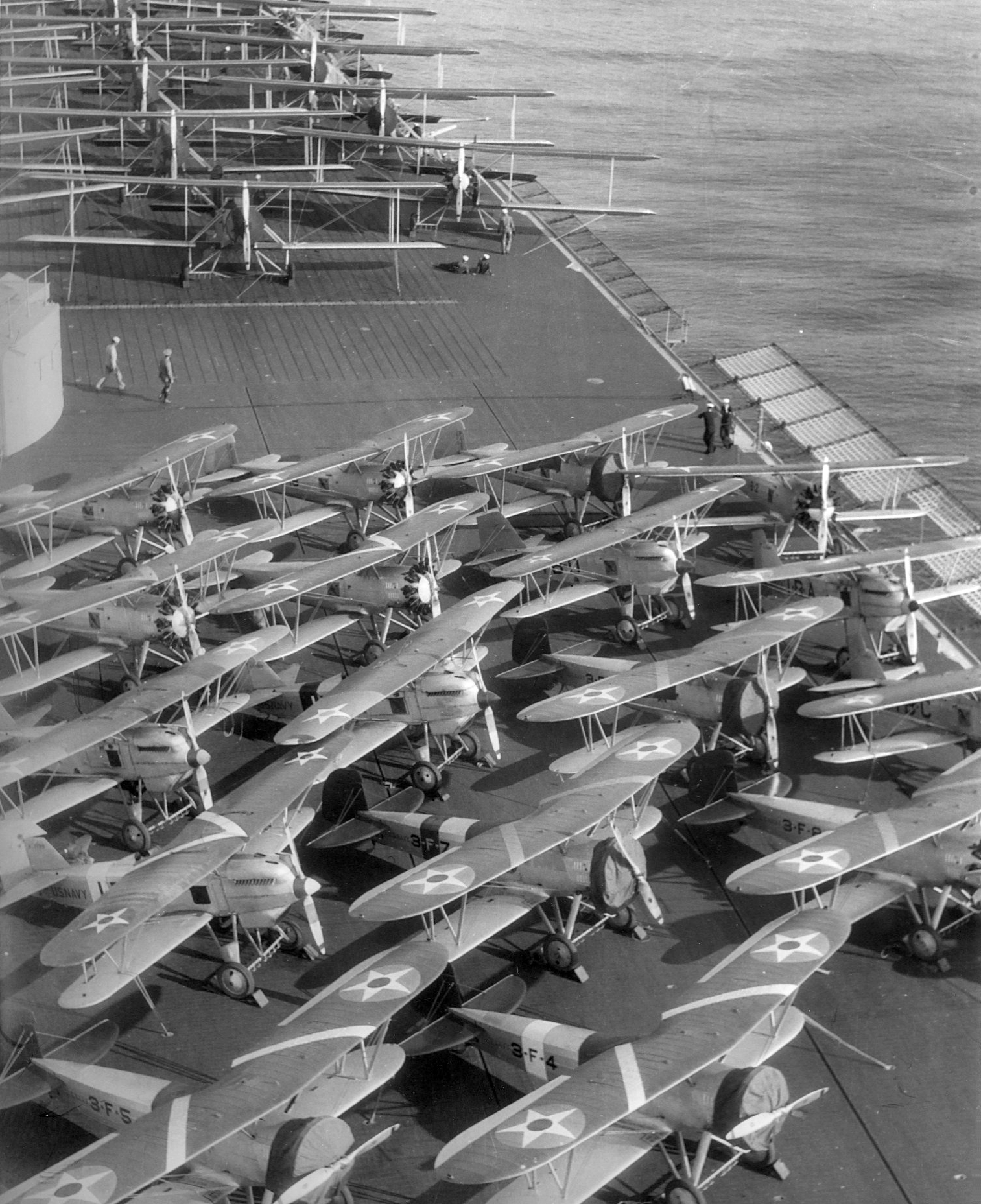
In 1925, the P-1 entered US navy service as the F6C. The F6C-2 and 3 models were modified with arrestor hooks and strengthened landing gear for use on early US aircraft carriers. These were the last aircraft with inline engines used on US carriers. Beginning with the F6C-4, the airframe was fitted with an increasingly powerful series of Pratt and Whitney radial engines. Air-cooled radials were mechanically simpler and easier to maintain at sea.
With the adoption of the radial engine in navy service, the plane began to change very noticeably. By 1932, the navy radial-powered Hawks line was developed into the F11C Goshawk, which featured aerodynamic landing gear spats and a cowling around the radial engine. This evolved into the BF2C-1, a carrier-born fighter-bomber, first delivered in 1934, which looks a bit like a pregnant guppy because of an enlarged forward fuselage that housed hand-cranked retractable landing gear.
Another branch of the Curtiss Hawk tree emerged when the design sprouted a second seat and a larger wing to become the Falcon series.. First introduced in 1925, the falcons were used by the army as trainers and attack planes, typically with a gunner in a second seat behind the pilot. They were also used as radial-powered observation planes dive bombers by the navy. The ultimate version was the radial-engined F8C Helldiver dive bomber variant, which was probably the Hawk variant that was furthest away from P-1 root. These were the planes that attacked King-Kong at the top of the Empire State Building in the 1933 film.
This is just a superficial overview of the type. An article written in 1934 counted "some thirty-five more or less distinct hawk types..." The Hawk airframe was fitted with skis to operate off snowy fields, and floats to operate as a seaplane . It was used to pioneer aircraft carrier operations, as well as naval dive bombing. Various versions of the two-seat Falcon variant were used as a mail carriers, with the front seat space used for storage. The hawk airframe was modified several times for racing, by both the American army and navy, sometimes pretty radically. It was fitted with a staggering variety of experimental engines, superchargers, cooling systems, and cowlings. It was exported around the world, from Cuba to Turkey, often in unique variants.
Despite their wide adoption, the Curtiss Hawks were rarely used in war. The notable exception was their Chinese service. Already close to obsolete when the first Hawk IIs were purchased by the Chinese government in 1933, they were badly outclassed by newer Japanese aircraft in the Sino-Japanese War that began in 1937.
American Century
At the beginning of the 20th century, the American military was small compared to the European powers. By it's end, it had grown into is the most disproportionately powerful military that has probably ever existed, at least in terms of wealth, resources, and technological sophistication. Within the field of aviation, the interwar period is especially interesting. During the First World War, the United States relied on France and Britain—mostly France—for its military aircraft. By the Second World War, practically every major allied power had adopted American aircraft to some extent, or would come to rely on them during the war.
The P-1 was an important step in this rapid development of the American military aircraft industry. It also represents a period when the tactical possibilities for using aircraft were rapidly changing, leading to many new ideas, and more than a few dead ends. The United States, with its enormous wealth and industrial capacity, played an ever greater role in this process of military experimentation.
The P-1 entered service in 1924, a year after its prototype, the PW-8, had flown. A decade later, though still in service, the airframe was close to obsolete. This was the rapid evolution of a technology in its infancy. Compare this to the current trillion-dollar F-35 program, whose prototype first flew in the year 2000 and is only now, eighteen years later, finishing its testing phase. The F-35 platform is expected to serve for another fifty years as its designers incrementaly upgrade and replace its enormous network of complex systems.
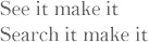
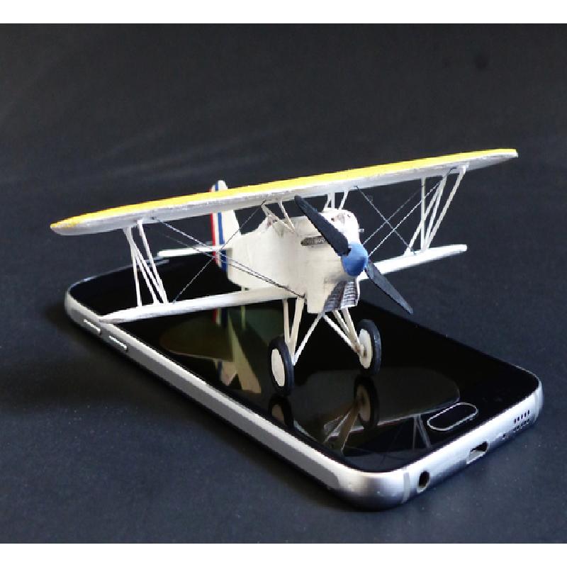
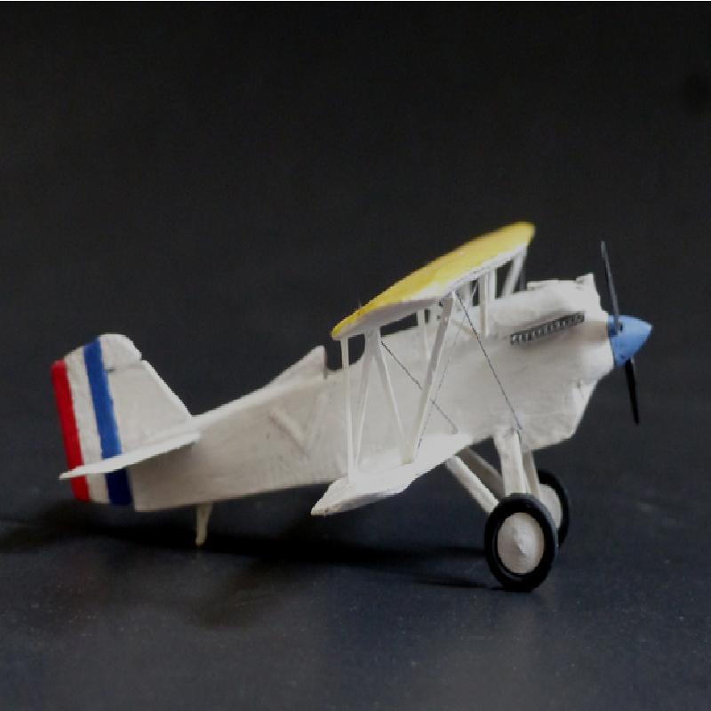
This model prints in a number of pieces that require gluing and assembly. Fine structures like struts are printed flat against the bed so that the come out nicely within scale. In it's current state, it should build up into something that looks convincingly like a Curtiss P-1A at 1/72 scale. If you have a .2 nozzle or an SLA printer, this should work nicely at 1/144.
Bi-plane models are hard to build because of the alignment between the upper and lower wings and the thin struts between them. This model comes with a set of jigs that let you position the upper wing and glue the struts relatively easily. Although FDM-printed PLA isn't as nice to work with as injection-moulded styrene, the material is cheap so making customized jigs and guides is an option.
Instructions:
To make this thing, you'll need, at minimum, some CA glue. A bit of 200 grit sandpaper and some small files would also be a good idea.
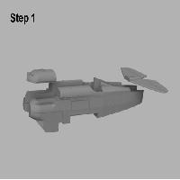
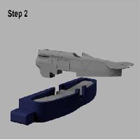
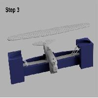
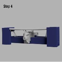
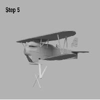
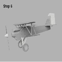
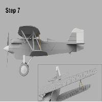
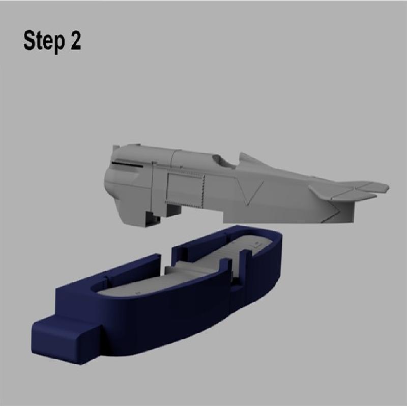
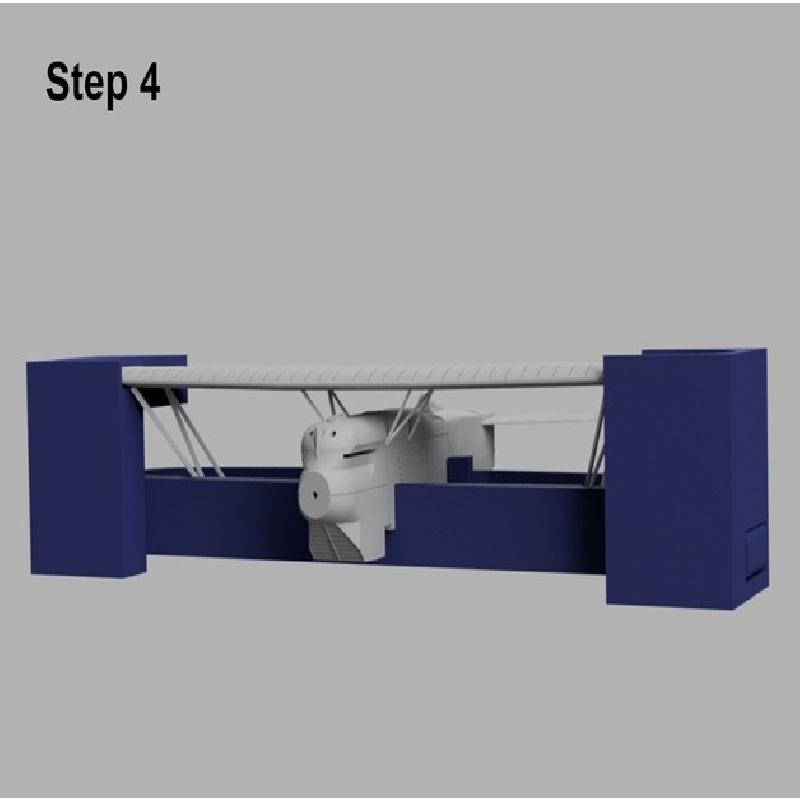
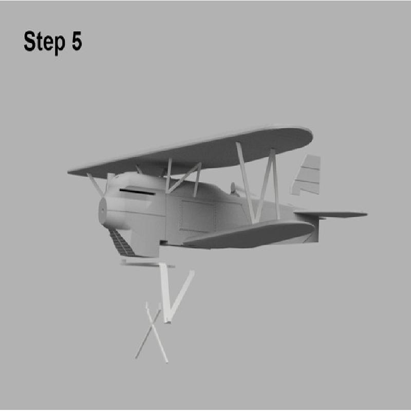
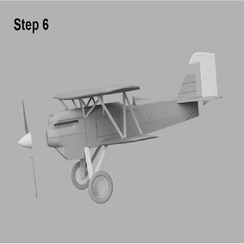
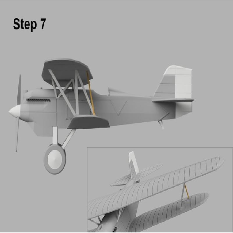
These steps are illustrated in the images above:
1) Glue the engine halves together. Glue on the engine cap and the horizontal stabilizer.
2) Place the lower wing inside the jig and glue the fuselage onto it.
At this point, you'll probably want to finish this section, the upper wing, and the other various pieces to the level that you want.
3) Slide the side supports onto the "Wing Guide" jig. Glue the main wing struts to the indentations in the lower wings. These should lean outwards so that their tops touch the corner of the side supports as illustrated. Make sure that the struts are facing the right way.
4) Put the top wing into place in the side supports. Now glue the top of the main struts to the upper wing. Try not use too much glue or you might glue the struts to the side supports If you do, just separate them with an Exacto knife and start over.
Glue the fuselage struts first to the small indentations in the fuselage, then to the upper wing. This can be a bit tricky, but you'll get the hang of it. Makeup tweezers are helpful for this sort of thing. Wait until the glue is set before removing the side supports. The wing structure is surprisingly sturdy once it's all glued together.
5) Bend the gear struts to loosen the hinges. Glue the gear struts into the recess at the base of the fuselage. Glue the gear cross into the two holes in the gear struts. Bend each side of the gear struts so that they touch the tips of the gear cross and glue them down.
Glue the vertical stabilizer in place.
6) Paint the wheels. They are in two parts so that you can main the tires and the hubs separately.
Glue the propeller blades into the propeller hub.
Glue on the wheels, rudder, and propeller.
Separate the two halves of the exhaust piece, paint them, and glue them into the sockets on either size of fuselage.
Fold the tail skid in half and glue it into the slot in the fuselage near the tail. You might want to trim this a bit with an X-Acto blade to get it to a convincing shape.
7) There are two more pieces—I've called this file "aileron rod" because these pieces probably actuate the ailerons. This prints in one piece that is cut in the centre. They sit vertical to the earth and tilted forward from the bottom wing to the lower side of the aileron.
There are all sorts of ways to paint a model. You can easily use inexpensive paints and supplies.
The easiest approach is to prime with a PVA glue diluted with a bit of water (I use Weldbond, though other brands might work), and brush painting with cheap craft acrylics.
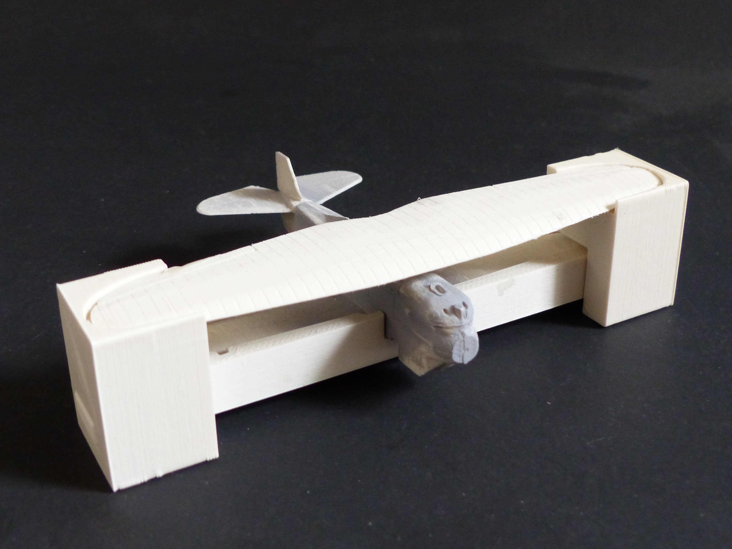
The model in the photo above was sanded (~200 grit) and the gaps between the pieces were filled with modelling putty. After brush painting as above, it was given a gloss coat of acrylic floor polish and lightly weathered using watercolour pencil thinned with water. Lastly, it was sprayed with a matte clear finish.
Rigging—bracing cables that add rigidity—was an essential structural component of aircraft of this era. It is impossible to convincingly produce these cables with any 3d printing technology that I know of, but fairly easy to do on your own.
There are a number of elastic products that modellers use to represent rigging and other wire structures at various scales. Here, I've used some elasticized thread from a dead sock.
Here are some instructions:
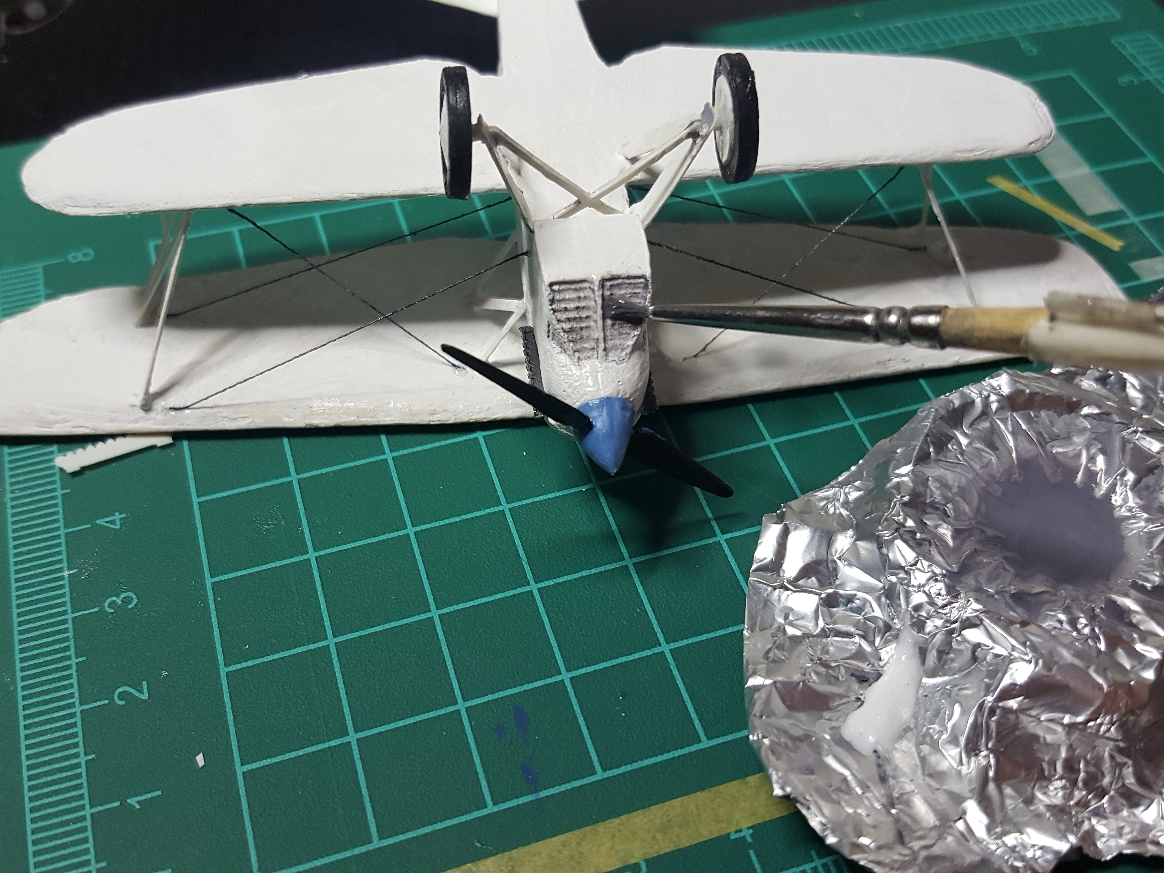
Cut your length of thread to length and glue one end into position with CA glue. It helps to cut the end cleanly and stiffen it with glue. Give this some time to harden.
Hold the other end in tension with a clamp a little beyond where you want to glue it down. I use my clothespin clamps with rubber tips. Use one or two toothpicks to dip the thread down into a dab of CA glue. Hold it there to the glue hardens. Trim the end with an X-Acto knife.
Once everything's in place, you can colour the rigging with a metallic marker or pen.
Tip: Use as little glue as necessary to get it the thread to stick in place. A small amount of glue will stick quickly and make your life easier. You can add more glue later to seal the thread in place.

